7XTP II CrossPoint Series • Installation
NOTE: See item
A
on figure 2 on page 4, figure 3 on
page 5, and figure 4 on page 6.
2
XTP power indicators — Indicate the status of the power
over XTP (PoX) provided to the endpoint as follows:
Lit green — The board is providing XTP power to the
endpoint.
Lit amber — XTP power is available, but disabled.
Blinking amber — XTP power is not available, but enabled.
Lit red — A wiring fault exists.
Unlit — The endpoint cannot receive power over XTP.
3
LAN connectors — As desired, connect a TP cable
between a host device or control LAN and this
connector for passive extension to the LAN
(Ethernet) connector on the connected endpoint (see
TP connectors on page 13 to wire the connector).
4
RS-232/IR Over XTP connectors — If desired,
connect serial RS-232 signals, modulated IR
signals, or both to these 3.5 mm, 5-pole captive
screw connectors for bidirectional RS-232 and IR
communications on the associated inputs (see RS-232 and
IR connectors on page 15 to wire the connectors).
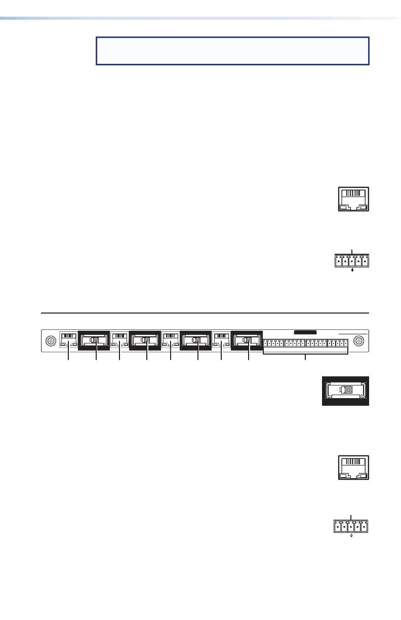
XTP CP 4i Fiber 4K (ber optic input board)
SIGLINK
XTP IN
LANLAN LANLAN
SIGLINK
XTP IN
SIGLINK
XTP IN
SIGLINK
XTP IN
OVER FIBER
RS-232
IR
Tx Rx GTxRx
RS-232
IR
Tx Rx GTxRx
RS-232
IR
Tx Rx GTxRx
RS-232
IR
Tx Rx GTxRx
5
XTP in connectors — Connect up to four fiber
optic cable between these ports and the Tx port
of a compatible Extron fiber optic transmitter.
This board uses small form factor pluggable
(SFP) modules with industry-standard LC fiber optics
connectors to provide reliable physical connectivity and
precise fiber core alignment.
3
LAN connectors — As desired, connect a TP cable
between a host device or control LAN and this
connector for passive extension to the LAN
(Ethernet) connector on the connected endpoint (see
TP connectors on page 13 to wire the connector).
4
RS-232/IR Over XTP connectors — If desired,
connect serial RS-232 signals, modulated
IR signals, or both to these 3.5 mm, 5-pole
captive screw connectors for bidirectional RS-232 and IR
communications on the associated inputs (see RS-232 and
IR connectors on page 15 to wire the connectors).
SIG LINK

 Loading...


