Index
Index - 2
hardware requirements
for components 1-4
for peripherals 1-5
hardware specifications
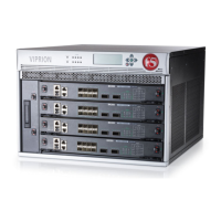
for J100 chassis 9-6
for PB100 blade 9-4
for PB200 blade 9-5
for VIPRION DC-powered chassis 6-6
hazardous substance restrictions
for China A-1, A-2
help, online 1-6
Hold mode 3-2
hot-swap components
and fan tray 5-5
hubs 1-5
I
indicator LEDs
and actions 4-2
and functions 4-1
and types 4-1
configuring 4-3
displaying node status 4-3
for alert conditions 4-3
for special conditions 4-4
indicators
See indicator LEDs.
installation of platform 2-1
interface media type 4-6
interface settings
displaying 4-5
interface status
displaying 4-5
intermittent Activity LED 4-4
J
J100 chassis 9-6
L
LCD component
and alerts 3-2
and indentations 5-8
removing 5-8
replacing 5-8
LCD menus
accessing 3-3
introducing 3-3
navigating 3-3
LCD panel 3-1
configuring 3-2
for Options menu 3-3
for Screens menu 3-5
for System menu 3-4
LED
behavior 4-1
for blade alarms 4-1
for chassis alarms 4-1
for chassis status 4-1
for network interfaces 4-8
for power supply 4-1
LED indicators
when green 4-4
when yellow 4-4
liquid crystal display
See LCD.
M
maintainence
and fan tray 5-5
maintenance
and blades 5-1
and LCD component 5-8
and power supply 5-6
media types
and attributes 4-6
setting 4-7
Menu mode 3-2, 3-3
menus on LCD panel 3-3
mixed cluster
and blade compatibility 2-2
and redundant system configuration’ redundant
system configuration
and mixed clusters 2-3
and trunk configuration 2-3
defined 2-2
N
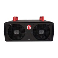
negative pressure fan system 7-1
network LED behavior
for RJ45 copper interfaces 4-8
for SFP optic interfaces 4-8
for SFP+ optic interfaces 4-9
for XFP optic interfaces 4-9
O
online help 1-6
optics modules 9-4, 9-5
Options menu 3-1, 3-3
P
peripheral hardware 1-5
platform
about 1-1
and cooling system 7-1
grounding 6-2
installing 2-1