11
Lt
50 50
Vp
A. ASSEMBLY OF IN-KIT AUTOMATED SYSTEMS
1A PREPARING THE SUPPORT PROFILE
Supportprofilesareavailableintwosizes:
4300 mm or 6100 mm.
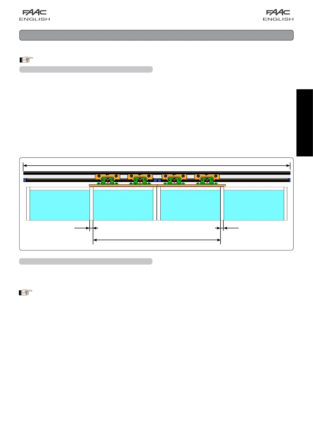
Cutthesupportprofiletomeasureusingthefollowingformula:
LT = Vp x 2 + 100
Where:
• Ltisthelengthofthesupportprofile
• VPisthetransitspace
• 100aretheoverlapmillimetersbetweentheleaves(50+50)
Thissectiondescribestheassemblyofthein-kitautomatedsystems.Afteryouhavepreparedthenecessaryprofiles,weadviseyou
toassembleandinstallatthesametime.
Automation free-standing refer to Chapter 21
fig. 10
1.1A SUPPORT PROFILE - SECURING ON WALL
Definetheexactheightpositionofthesupportprofile,considering
thedimensionsoffig.4andfig.6;fordoorswithglassleaves,
refertofig.5.
The cross beam must be fastened parallel to the
floor.
Initiallyfixthesupportprofileonaverticalslotatoneend,and
on a horizontal slot at the other end (using M8 screws and
appropriateexpansionplugswhicharenotsupplied)andlevel
paralleltothefloor.Fastencentrally,liftingthesupportprofilewith
forcetoalignthethreesecuringpoints.Carryouttheremaining
fastenings.fig.11
 Loading...