12
200200
30
30
30
37,5
a
b
c
a
80
fig. 12
fig. 13
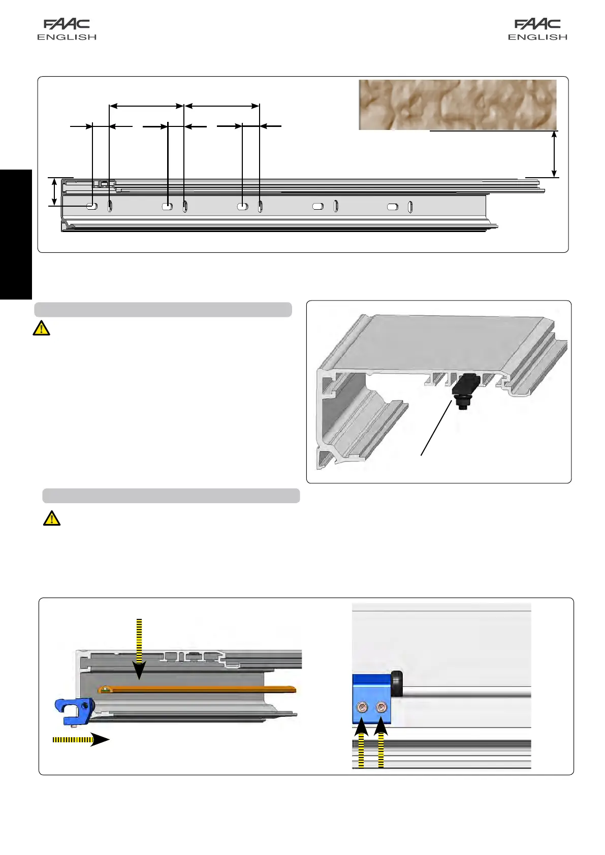
1.2A FITTING THE ELECTRONICS MODULE ROD
Themechanicalstopsare2forsingleleafandto4anddouble
leaf.Inserttheslidingguideontheprofilefig13-a and insert
sidewaysthemechanicalstopfig13-b.
Thensecureitwiththe2Allenscrewsfig.13andfig.14-c .
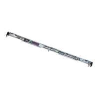
1.3A ASSEMBLING THE SLIDING GUIDE
Important:therodwithtie-rodsbefittedbeforesecuring
thesupportprofiletothewall.
Iftherodwasnotfitted,youcanfitthesmallplateswiththe
relevantscrewsinsteadofit
Inserttherodwithtie-rodssidewaysonthesupportprofile
inordertofittheelectronicsmodulefig.12a
Important:Thecentralandsidemechanicalstopsmust
befittedsideways,aftertheslidingguide,asfirstelement
oftheA140AIRdoor.
fig. 11
 Loading...