36
1
2
3
4
5
6
7
8
9
10
11
12
13
J7
I-DET
E-DET
KEY
EMERG1
EMERG2
-FAILSAFE
OUT1
+24V
+24V
GND
GND
P
P
1
2
3
4
5
6
7
8
9
10
11
12
13
J7
I-DET
E-DET
KEY
EMERG1
EMERG2
-FAILSAFE
OUT1
+24V
+24V
GND
GND
P
P
XMA1 ON
XMA1 ON
XBFA ON
XBFA ON
P1=Cc
1F=Y
P2=Oc
2F=Y
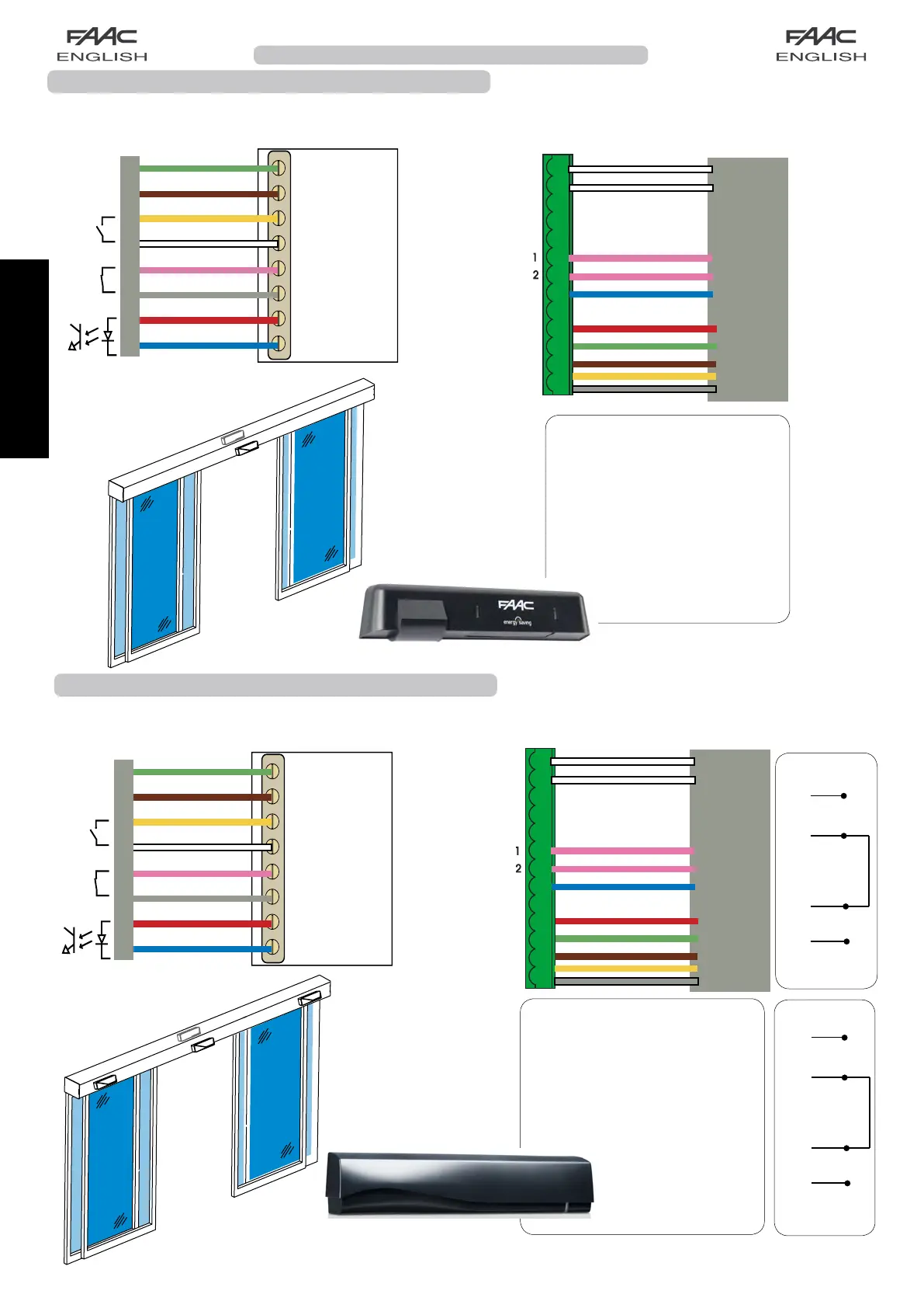
Programming from Display
for 2 XMA1 ON sensors serially
connected on input P1 and
2 XBFA ON sensors in series
on input P2 :
Connection of XMA1 ON and XBFA ON safety detectors
TheXMA1ONsensorisamonitoredopeningandclosingsafetydetectorandtheXBFAONsensorisamonitored
opening safety detector, compliant with the EN16005 standard. Below are the connections of 2 sensors on J7 connector
automatic door board:
12-24 V
AC-DC
XMA1ON
XMA1 ON + XBFA ON
Connection of safety detector XMA1 ON
TheXMA1ONsensorisamonitoredopeningandclosingsafetydetector,conformingtotheEN16005standard.
Below are the connections of 2 sensors on J7 connector automatic door board:
Connection terminal J7
12-24 V
AC-DC
Green
Brown
Yellow
White
Pink
Grey
Supply
Red
Blue
test output
entry
security
entry
opening
XMA1ON
XMA1 ON
White
White
Pink
Pink
Blue
Red
Green
Brown
Yellow
Grey
XMA1 ON
XMA1 ON
P1=Cc
1F=Y
P2=Cc
2F=Y
Programming from Display
for 2 XMA1 ON sensors con-
nected on inputs P1 and P2:
XMA1 ON
XBFA ON
*
*
XMA1 ON (2)
Pink
Pink
Grey
Grey
12 (J7)
6 (J7)
XBFA ON (2)
Pink
Pink
Grey
Grey
7 (J7)
Green
Brown
Yellow
White
Pink
Grey
Red
Blue
White
White
Pink
Pink
Blue
Red
Green
Brown
Yellow
Grey
*
*
*
Supply
test output
entry
security
entry
opening
 Loading...