FX15 Controller Technical Bulletin
Table 7: Digital Inputs Powered by 24 VAC
24 VAC, Digital Inputs Power Supply
Digital Inputs Power Supply Common
Digital Input 8, Voltage-Free contact
Common Reference, Voltage-Free contact
Note: The numbers inside the parentheses are the FX15 controller
terminal numbers.
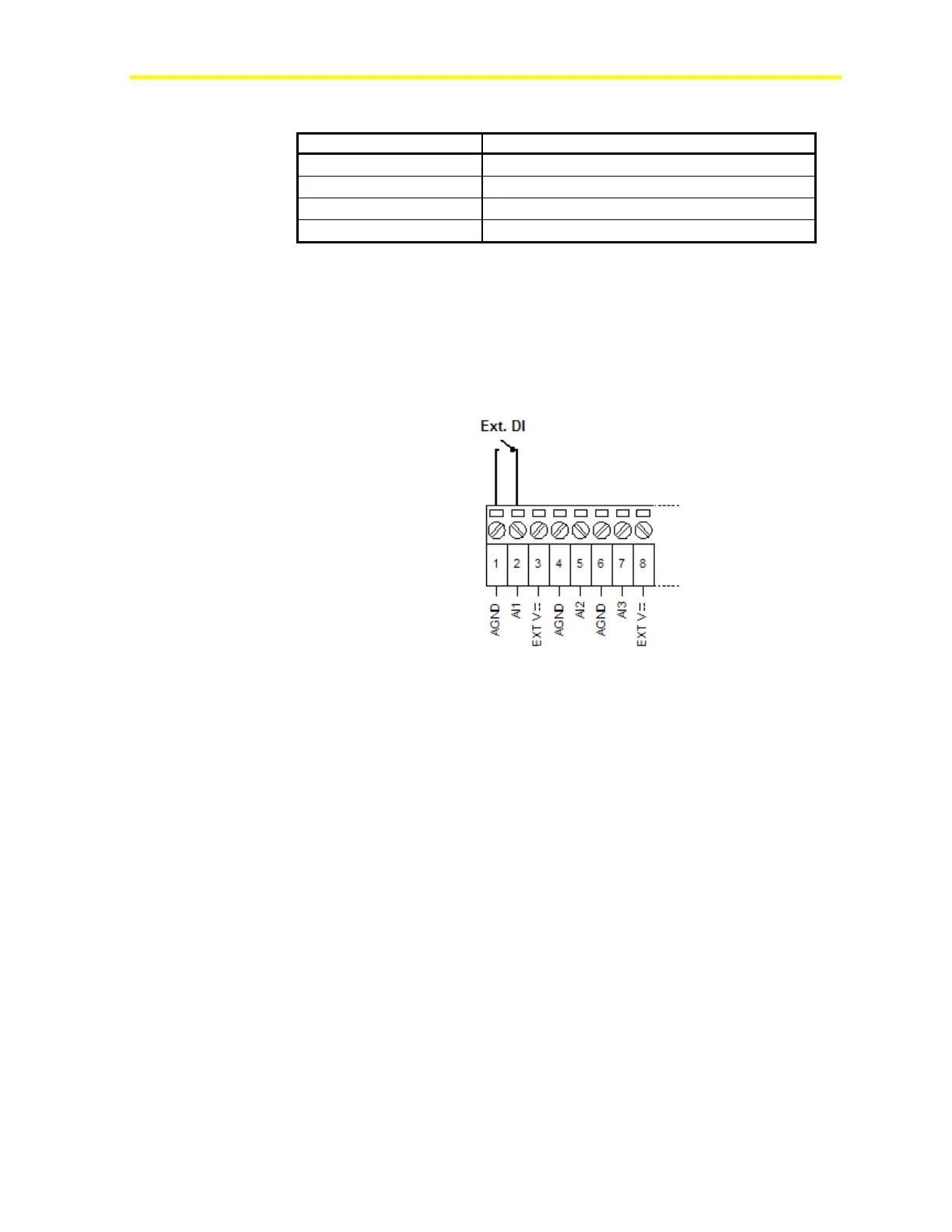
Using Analog Inputs as Digital Inputs
If you need more than 8 digital inputs, the FX15 controller allows you
to use an analog input as a digital input.
Figure 37: Digital Input Connection Diagram
The Analog Input needs to be properly configured in FX Tools to read
the digital input.
Analog Outputs
The FX15 controller provides up to four, 0-10 VDC, 1.5 mA maximum,
opto-isolated analog outputs. The Analog Output objects provide the
interface between the four hardware Analog Output channels and the
control application. See I/O Technical Details for the complete FX15
controller I/O table.
Use the application software to configure the analog outputs for direct
acting or reverse acting.
Use the high limit (MaxOutput) and low limit (MinOutput) values to
limit the output signal.
Powering and Connecting the Analog Outputs
Power the analog outputs separately, through Terminals 79 and 80, to
ensure microprocessor isolation from the controller power supply
(see Figure 39).