FX15 Controller Technical Bulletin
Installation
This chapter describes the process of installing an FX15 controller.
179 (7.05)
44
(1.73)
75 (2.95)
215 (8.46)
1
22
(4.
8)
14
2 (5
.59
)
35
(
1
.3
8)
66 (2.6)
49 (1.93)
BB
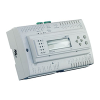
Figure 2: Mounting Dimensions for FX15 Controller, mm (in.)
(Shown with Integral User Interface and Screw Connectors)
46.5 (1.83)
180.5 (7.11)
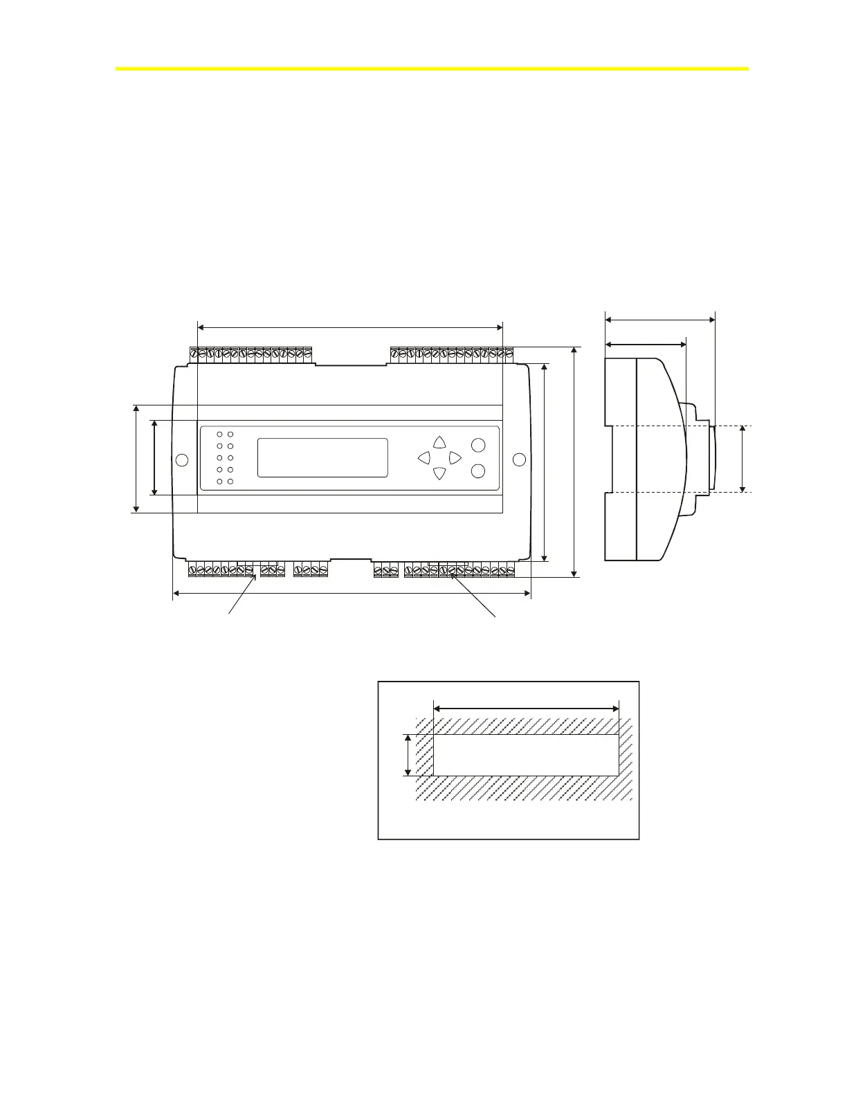
Panel cut-out
Figure 3: Panel Cut-Out Dimensions for User Interfaces, mm (in.)
Two different types of terminal connectors are available: spring clamp
or screw connectors. The screw connectors are included, whereas the
spring clamp connectors must be ordered separately. For details, see
Ordering Codes.