FX15 Controller Technical Bulletin
Technical Specifications
I/O Technical Details
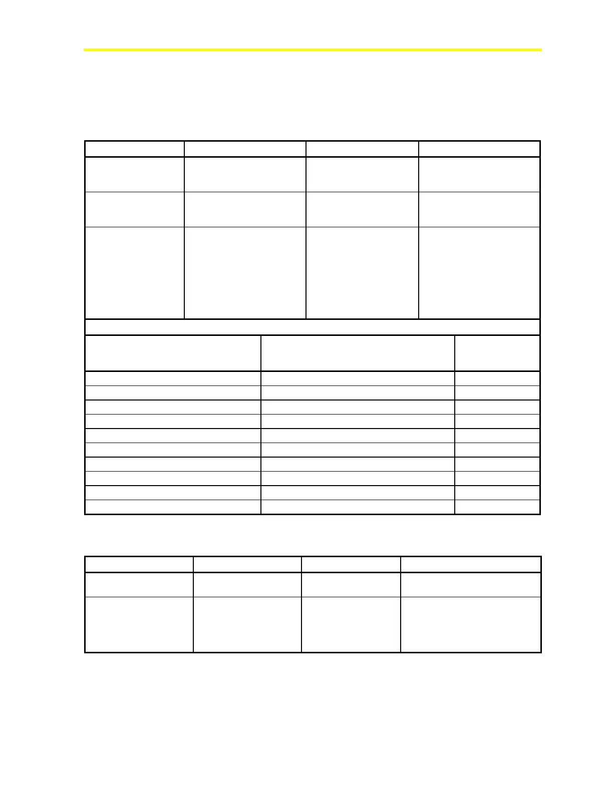
Table 18: Analog Input (AI)
AI1, AI2, AI3, AI4, AI5, AI6 See Figure 30. Software configurable.
Application: temperature,
humidity, pressure
EXT-VDC +16 V, 80 mA Directly power from the
controller. Maximum four
0-20/4-20 mA sensors
EXT-VDC = +16 V, 80 mA
ratiometric sensors,
with AVPS or
0-10 V, 0/4 - 20 mA Sensors
with EXT-VDC.
The selection between AVPS
and EXT-VDC is done
through jumpers.
List of Available Sensor Input
@ 20°C (68°F)
-45 to 120 °C (-49 to 248°F)
Ni1000 Johnson Controls Extended
20 to 287°C (68° to 548.6°F) +/- 0.5° C (0.9°F)
-50 to 160°C (-58 to 320°F)
-60 to 180°C (-76 to 356°F)
-50 to 605°C (-58°F to 1121°F)
A99
-50 to 110°C (-58 to 230°F) +/- 0.5° C (0.9°F)
-40 to 150°C (-40 to 302°F)
10 to 90% of supply voltage
Table 19: Digital Input (DI)
DI1, DI2, DI3, DI4, DI5,
Potential free
DI V~ Hot
DI V~ Com
24 VAC/DC Power supply for the Digital
Inputs. Must be used to
maintain the opto-isolation of a
separate power supply from the
one used for the controller.