Drive modules
188
3.
DRIVE MODULES
Modular drives
126
DDS
HARDWARE
Ref.1310
Function of the connectors
Power connector
The power connectors located on top of each drive module are used to
connect the motor.
The ground connection of the cable shields in made from the vertical plate
next to the connectors.
The power bus input is located at the bottom of the modules and under
the screwed-on lid. The drive needs 456-800 V DC which can vary de-
pending on the mains voltage and the load. The power supply module is
in charge supplying this voltage.
2 plates are supplied with each module for this connection and another
one for connecting the chassis with each other.
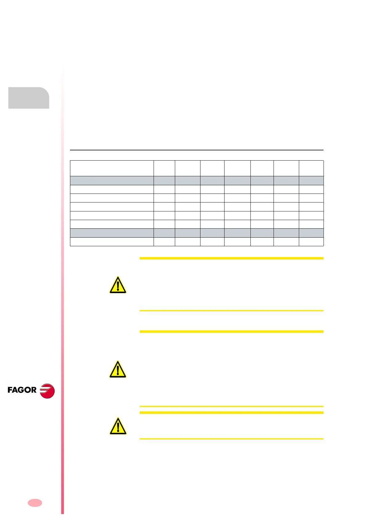
The following table shows the values for gap, tightening torque, pole sec-
tions (wire entry holes) and other data regarding these screw-on connec-
tors according to drive model:
T. H3/6 Technical data of the terminals of the power connector.
AXD/SPD/MMC 1.08
1.15
1.25 1.35 2.50
2.75
2.85 3.100
3.150
3.200
3.250
Connector data
Gap (mm) 7.62 7.62 10.16 10.16 10.16 - -
Min/max tightening torque (Nm) 0.5/0.6 0.7/0.8 1.2/1.5 1.7/1.8 1.7/1.8 6/8 15/20
Screw thread M3 M3 M4 M4 M4 M6 M8
Min./max. section (mm²) 0.2/4 0.2/6 0.75/6 0.75/16 0.75/16 16/50 35/95
Rated current In
(A) 20 41 41 76 76 150 232
Wire data
Length to strip (mm) 7 10 12 12 12 24 27
WARNING. When connecting the drive module with its corresponding mo-
tor connect terminal U of the drive module with the terminal correspond-
ing to the U phase of the motor. Proceed the same way to connect the
terminals V-V, W-W and PE-PE. If they are not connected like this, it
could perform poorly. The cable must have a metallic shield that must be
connected to the ground terminal of the drive and to that of the motor in
order to comply with EU directives.
WARNING. Observe that before handling these terminals, you must pro-
ceed as indicated and in the following order:
Disconnect the mains voltage at the electrical cabinet.
Wait a few minutes before handling these terminals.
The power supply needs time to decrease the voltage of the power bus
down to safe values (< 42 V DC). The green indicator DC BUS ON being
turned OFF does not mean that the power bus may be handled or manip-
ulated. The discharge time depends on the number of elements connect-
ed and it is about 4 minutes.
WARNING. Please note that the STO (Safe Torque Off) safety function
does not imply an electrical power off. There is still voltage at the DC bus.
Ignoring this warning may cause electric shock.