Drive modules
188
3.
DRIVE MODULES
Compact drives
160
DDS
HARDWARE
Ref.1310
CMC 1.08/1.15
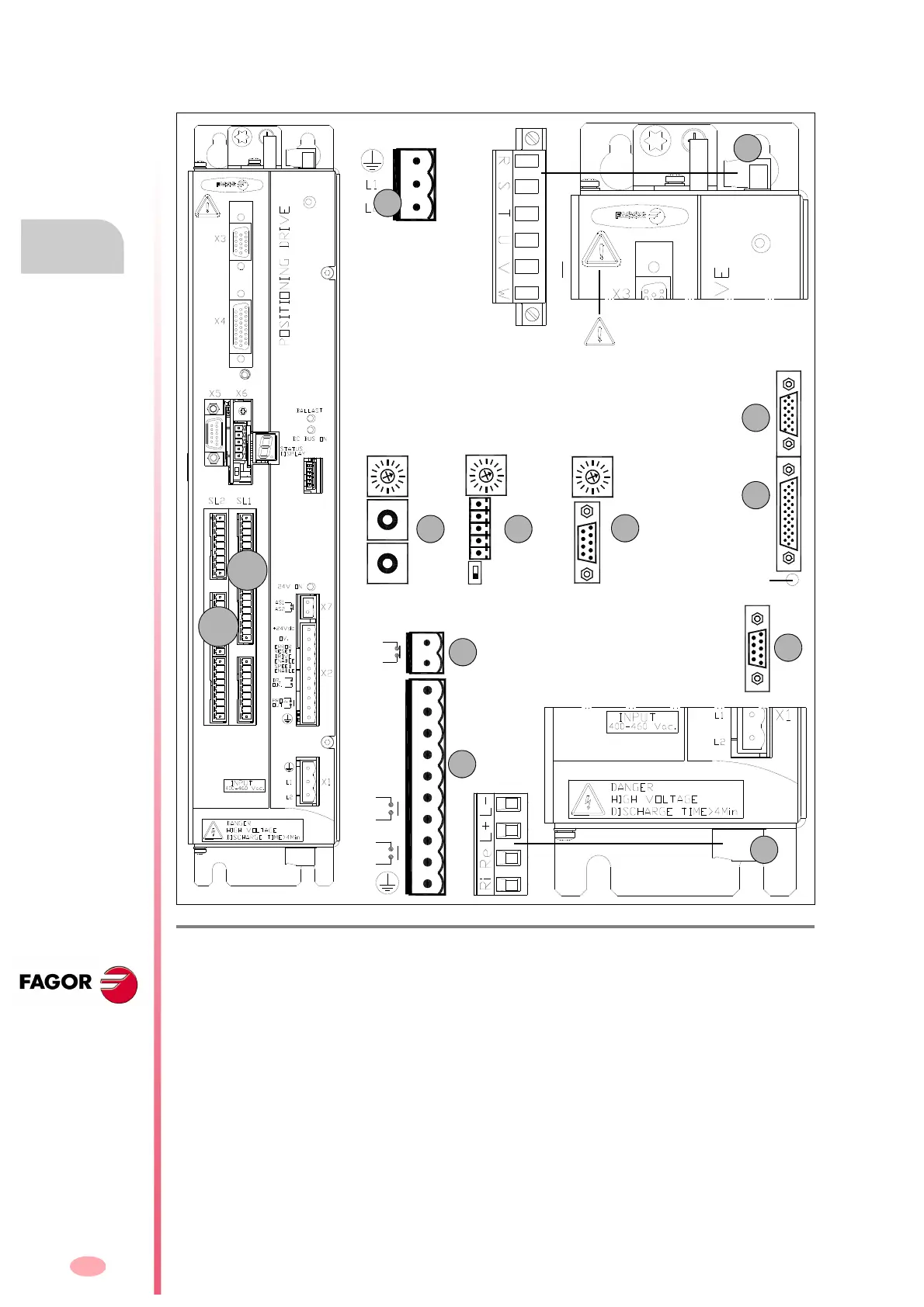
These drive modules have the following connectors:
F. H3/113
Connectors of “CMC 1.08/1.15” compact drives.
1. Power connector for motor (U, V, W) and mains connection (R, S, T).
2. Connector for the internal (Ri) (only on “1.08/1.15” models) or external (Re) Ballast resistor and for
accessing the power bus (L+, L-).
X1. Connector for the internal 24 V DC power supply (two phase 400-460 V AC).
X2. Connector for the basic control signals.
X3. Connector with two possible uses:
• as output of the encoder simulator.
• as input of the direct feedback for the position loop.
X4. Connector for motor feedback connection (encoder).
X5. Connector for RS-232 serial line connection.
X6.
Possible connectors that may be located in this position:
• SERCOS
a
or CAN
b
interface connector (always with X5).
• Connector for RS-232/422
c
serial line connection (never with X5).
X7. Connector for external acknowledgment of the status of the integrated safety relay.
SL1.Slot for the cards A1, 16DI-8DO and 8DI-16DO.
SL2.Slot for the cards 16DI-8DO and 8DI-16DO.
CANSERCOS RS422
(a) (b) (c)
NODE
SELECT
NODE
SELECT
0
1
0
4
8
4
0
8
0
4
8
1
2
3
4
5
1
9
NODE
SELECT
OUT
IN
X3
X4
X5
RESET button
Top
view
Bottom
view
BOOT button.
Software update and SER-
COS/CAN.Transmission
speed selection.
1
2
X1
Warning. AC touch current greater
than 3.5 mA. Install a ground wire with
a section of at least 10 mm² Cu or 16
mm² Al.
SL1
SL2
Possibilities:
X5.Serial line RS-232 + [X6.SERCOS
(a)
or X6.CAN
(b)
]
OR X6.Serial line RS-232/422
(c)
- without X5 -
ERROR
RESET
OV.
DRIVE
SPEED
DR.
+24Vdc
ENABLE
ENABLE
O.K.
OUT
PROG.
AS1
AS2