Drive modules
DRIVE MODULES
Compact drives
3.
161
DDS
HARDWARE
Ref.1310
CMC 1.25
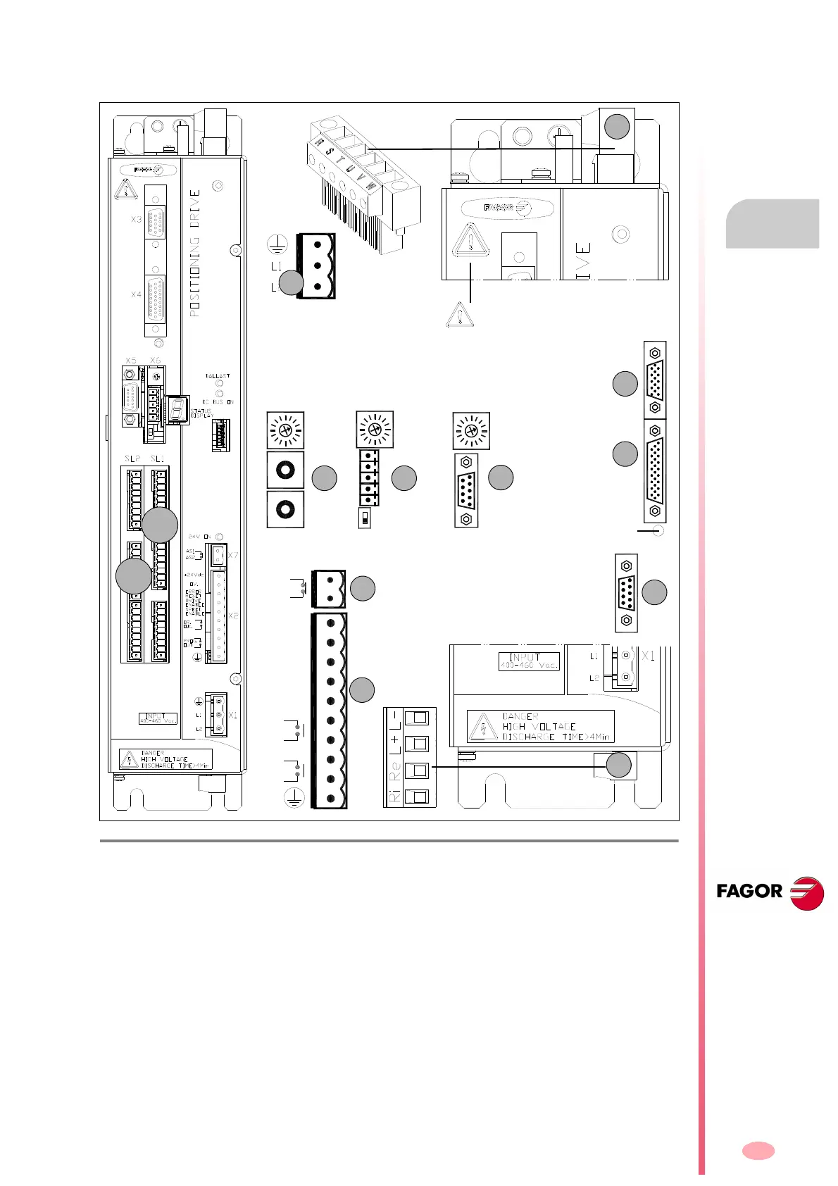
These drive modules have the following connectors:
F. H3 /11 4
Connectors of “CMC 1.25” compact drives.
1. Power connector for motor (U, V, W) and mains connection (R, S, T).
2. Connector for the external Ballast resistor (Re) and for accessing the power bus (L+, L-).
Remember that (Ri) makes no sense in these drives.
X1. Connector for the internal 24 V DC power supply (two phase 400-460 V AC).
X2. Connector for the basic control signals.
X3. Connector with two possible uses:
• as output of the encoder simulator.
• as input of the direct feedback for the position loop.
X4. Connector for motor feedback connection (encoder).
X5. Connector for RS-232 serial line connection.
X6.
Possible connectors that may be located in this position:
• SERCOS
a
or CAN
b
interface connector (always with X5).
• Connector for RS-232/422
c
serial line connection (never with X5).
X7. Connector for external acknowledgment of the status of the safety relay.
SL1. Slot for the cards A1, 16DI-8DO and 8DI-16DO.
SL2. Slot for the cards 16DI-8DO and 8DI-16DO.
CANSERCOS RS422
(a) (b) (c)
NODE
SELECT
NODE
SELECT
0
1
0
4
8
4
0
8
0
4
8
1
2
3
4
5
1
9
NODE
SELECT
OUT
IN
Possibilities:
X5.Serial line RS-232 + [X6.SERCOS
(a)
or X6.CAN
(b)
]
OR X6.Serial line RS-232/422
(c)
- without X5 -
X6 X6
X6
Bottom
view
2
X3
X4
X5
BOOT button.
Software update and SER-
COS/CAN.Transmission
speed selection.
ERROR
RESET
OV.
DRIVE
SPEED
DR.
+24Vdc
ENABLE
ENABLE
O.K.
OUT
PROG.
AS1
AS2
X7
X2
Warning. AC touch current greater
than 3.5 mA. Install a ground wire with
a section of at least 10 mm² Cu or 16
mm² Al.
SL1
SL2