Drive modules
DRIVE MODULES
Compact drives
3.
169
DDS
HARDWARE
Ref.1310
Other functions
The “Prog. Out” contact (pins 8 and 9) is a user programmable output by
means of an internal parameter of the drive. See parameter OP5 in chap-
ter 13 of the “man_dds_soft.pdf” manual.
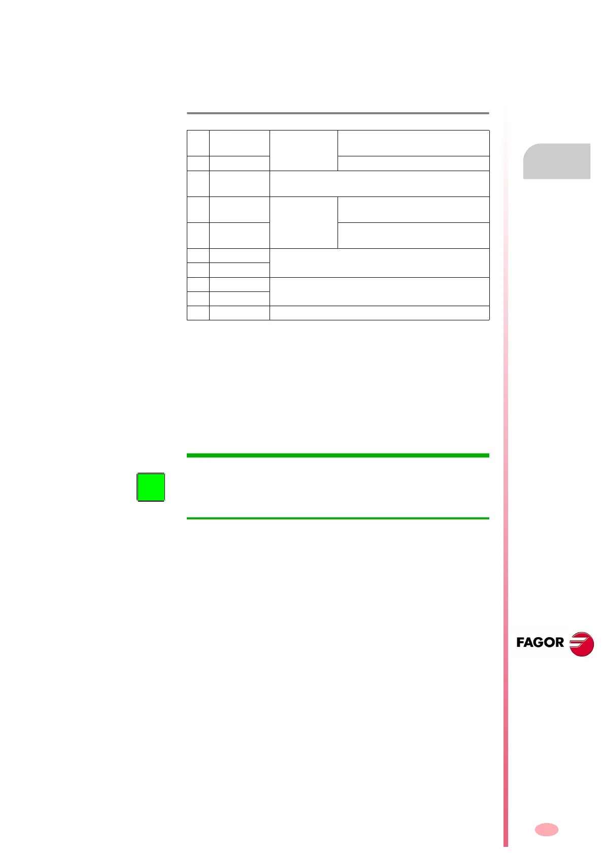
The description of the pins of this connector is:
SPEED ENABLE AND DRIVE ENABLE
Normal operating mode
1. Activate the Drive Enable and Speed Enable inputs (24 V DC) in the
desired order. Before activating, the Soft Start process (smoothly
reaching the power bus voltage) must be over. The motor will have
torque only when Drive Enable is active and there is voltage at the
power bus. The motor speed will be controlled with a command when
the Speed Enable function is active.
2. The motor will respond to all analog command variations only while
both inputs (Drive Enable and Speed Enable) are at 24 V DC. If any
of them is deactivated, the following will happen. See the operation
modes in figure
F. H3/119.
Deactivation of the Drive Enable input
The Drive Enable input lets the current circulate through the motor stator
windings. When it is powered with 24 V DC the current is enabled and the
drive can work.
If the Drive Enable input drops to 0 V DC (no voltage), the power circuit is
off and the motor will have not torque, hence not being governed and will
turn freely until it stops by friction.
Deactivation of the Speed Enable input
When the Speed Enable input is set to 0 V DC, the internal velocity com-
mand follows the stop ramp set by parameter and:
Situation 1
The torque is kept active by braking the motor. When it stops, variable
SV5 (S00331) is activated. The motor has stopped in a time period
shorter than the one indicated by parameter GP3 (F00702). The
torque is canceled and the rotor is free.
T. H3/24 Description of the pins of connector X2 of the compact drive.
1
+24 V DC
(OUT)
Power supply
selection
Positive voltage output
(24 V DC, 100 mA).
2 0 V. (OUT) Reference 0 V.
3
ERROR
RESET
System error reset input
(24 V DC), (4.5-7 mA).
4
DRIVE
ENABLE
Control signals
Motor current enable
(24 V DC).
5
SPEED
ENABLE
Drive speed enable
(24 V DC).
6 DR. OK. Module status contact
(open when failure)
7 DR. OK.
8 PROG. OUT
Programmable internal contact
Limit: 1 A at 24 V DC.
9 PROG. OUT
10 CHASSIS Chassis connection
INFORMATION. Activating the Drive Enable function requires to be re-
quested by the system in three different ways. They are: Electrical signal
at connector X2, variable BV7 (F00203), and variable DRENA of the PLC
when using the
SERCOS or CAN interface. It could be deactivated
through any of them.