Drive modules
188
3.
DRIVE MODULES
Compact drives
168
DDS
HARDWARE
Ref.1310
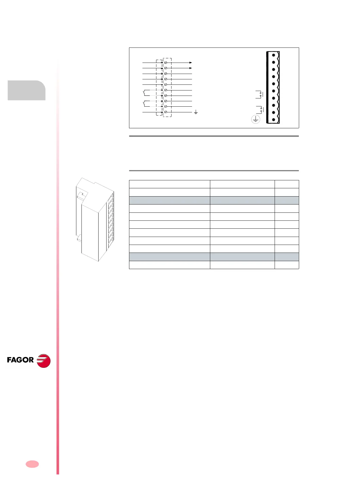
X2 connector
10-pin connector of the compact drive and integrates the functions of the
power supply and the modular drive.
The following table shows the values for gap, tightening torque (wire en-
try holes) and other data regarding the screw-on terminals of the aerial
plug-in connector for X2 according to drive model:
Specific of the power supply
With the Error Reset input (pin 3), it possible to remove the errors at a
compact drive. See “resettable errors” of chapter 14 of the
“man_dds_soft.pdf” manual. Hence, activating this input (24 V DC) elimi-
nates the resettable errors.
If the cause of the error persists, the status display will show the same er-
ror again.
But if it is a major error, it can only be eliminated by powering the unit off
and back on.
Pins 1 and 2 offer a 24 V DC output for the user.
The maximum output current is 100 mA.
Specific functions of the modular drive
Control signals. With the “Drive Enable” and “Speed Enable” inputs (pins
4 and 5) together with the velocity command, it is possible to govern the
motor.
The consumption of these control signals is between 4.7 and 7 mA.
The following page describes the behavior of the drive depending on
these control signals.
The “Drive Ok” contact (pins 6 and 7) will stay closed as long as the com-
pact drive runs properly.
F. H3/118
Connector X2. Control.
T. H3/23 Technical data of the aerial plug-in connector for X2.
ACD/SCD/CMC SCD
1.08/1.15/1.25/2.35/2.50 2.75
Connector data
Nr of poles 10 10
Gap (mm) 5.00 5.00
Min/max tightening torque (Nm) 0.5/0.6 0.5/0.6
Screw thread M3 M3
Min./max. section (mm²) 0.2/2.5 0.2/2.5
Rated current In
(A) 12 12
Wire data
Length to strip (mm) 7 7
RESET
ERROR
+24VDC
OV.
O.K.
PROG.
ENABLE
SPEED
ENABLE
DR.
DRIVE
OUT
OP5 [F01411]
PROG OUT
DRIVE OK
SPEED ENABLE
DRIVE ENABLE
ERROR RESET
0 VDC
+24 VDC
1
2
3
4
5
6
7
8
9
10