Selection criteria
232
5.
SELECTING CRITERIA
Asynchronous spindle motor and servo drive selection
212
DDS
HARDWARE
Ref.1310
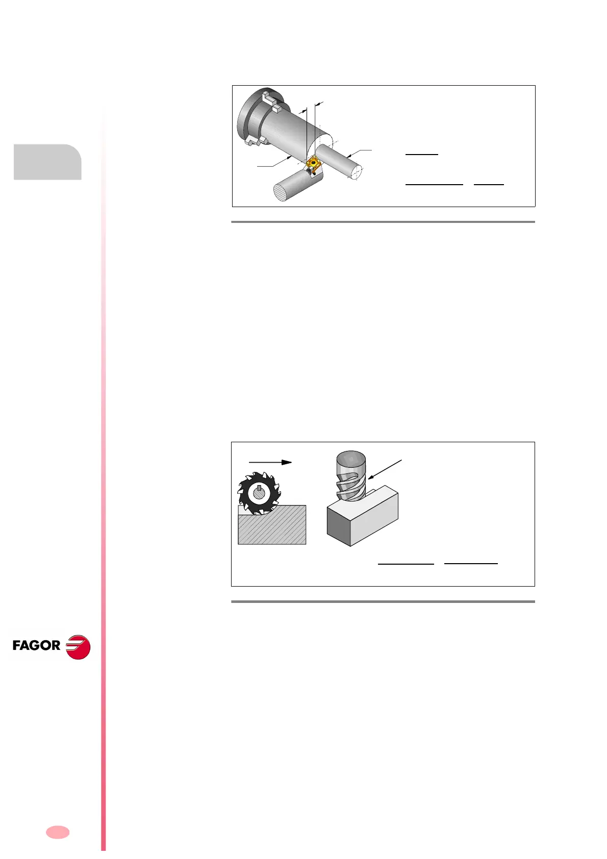
For lathe work, a cutting blade forces against the part to be machined,
while this is turning. See figure
F. H5/3.
The power required, Pc is calculated as follows:
In the case of a milling machine, the cutter is mounted on the spindle it-
self and turns with this to cut the material. See figure
F. H 5/ 4 .
The power required, Pf is calculated as follows:
F. H5/3
Machining for lathe. Cutting power.
V
Cutting speed in m/min
K
s
Relative cutting resistance in N/mm²
d
Cutting depth in mm
L
Length of the blade, or feedrate per full turn in mm
D
Diameter of the part machined in mm
N
s
Spindle turning speed in rpm
c
Mechanical efficiency (varies from 0.7 to 0.85)
S
c
Cutting efficiency. Cutting volume per kilowatt every minute
in (cm³/kW)/min
F. H5/4
Machining for mill. Cutting power.
K
s
Relative cutting resistance in N/mm²
d
Cutting depth in mm
W
Cutting width in mm
f
Feedrate in mm/min
N
s
Spindle turning speed in rpm
f
Mechanical efficiency (varies from 0.7 to 0.8)
S
f
Cutting efficiency. Cutting volume per kilowatt every minute
(cm³/kW)/min
V =
·d·N
s
1000
(m/min)
P
c
=
K
s
·d·L·v
60·1000·
c
=
d·L·v
S
c
·
c
(kW)
P
f
=
K
s
·d·W·f
60·1000²·
f
=
d·W·f
1000²·S
f
·
f
(kW)