Selection criteria
232
5.
SELECTING CRITERIA
Power supply selection
226
DDS
HARDWARE
Ref.1310
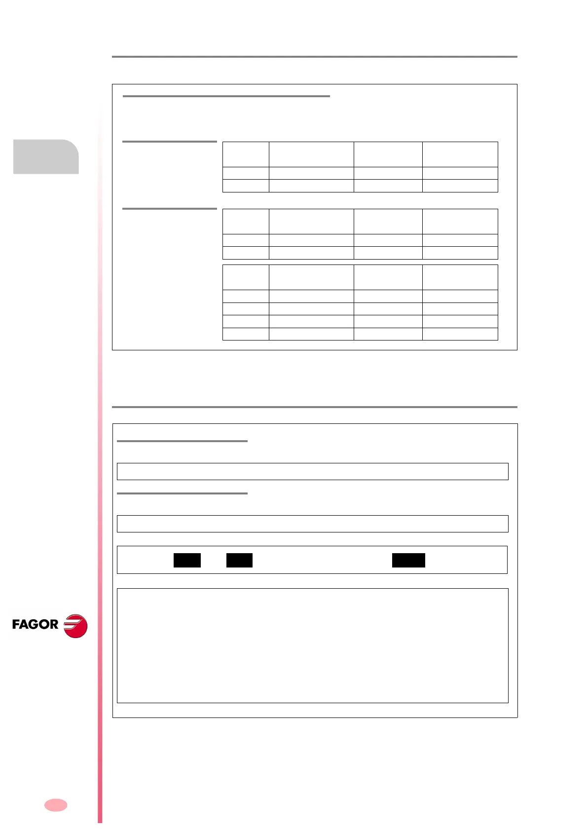
3. The range of FAGOR power supplies that may be selected is:
4. Use the following sheet to calculate the input transformer, and the section of the mains ca-
ble
.
T. H5/12 Power supplies of the FAGOR catalog. They indicate: Rated power, admitted mains voltage
and whether it outputs 24 V DC or not.
T. H5/13 Power of the input transformer.
NON
REGENERATIVE
Model Output power
S1
Input voltage Integrated 24V
power supply
PS-25B4 25 kW 400-460 V AC Yes
PS-65A 65 kW 400-460 V AC No
REGENERATIVE
Model Output power
S1
Input voltage Integrated 24V
power supply
XPS-25 25 kW 400-460 V AC Yes
XPS-65 65 kW 400-460 V AC Yes
Model S1/S6-40% output
power
Input voltage Integrated 24V
power supply
RPS-20 20/26 kW 400-460 V AC Yes
RPS-45 45/59 kW 400-460 V AC Yes
RPS-75 75/97 kW 400-460 V AC Yes
RPS-80 80/104 kW 400-460 V AC Yes
RANGE OF FAGOR POWER SUPPLIES
MAINS VOLTAGE
The FAGOR DDS servo drive system requires a mains voltage between 400 and 460 V AC
TRANSFORMER
A power transformer or auto-transformer must be used
NOTE. When using an isolating transformer, the secondary must have a star connection and its
mid point must be accessible so it can be connected to ground. This means that the output volt-
age of the transformer/autotransformer is maintained for the indicated apparent power.
Note
that
if the system has an XPS power supply, the rated power Pm of cell (2) of the previous
expression corresponds to the sum of the Pn's of all the asynchronous spindle motors of the
system, whose value is the result of applying the expression
Pn = 1.4·Pmax for each of them
and then adding them all.
Pmax will be the motor's maximum braking power and it may be,
in general, close to the power of the asynchronous spindle motor in S6.
If it is a PS
power supply
, cell (2) will register the value obtained from the table F. H 5/ 7, table F. H5/ 8 or
table
F. H5/9 accordingly.