Cables
CABLES
RS-232 serial line
7.
263
DDS
HARDWARE
Ref.1310
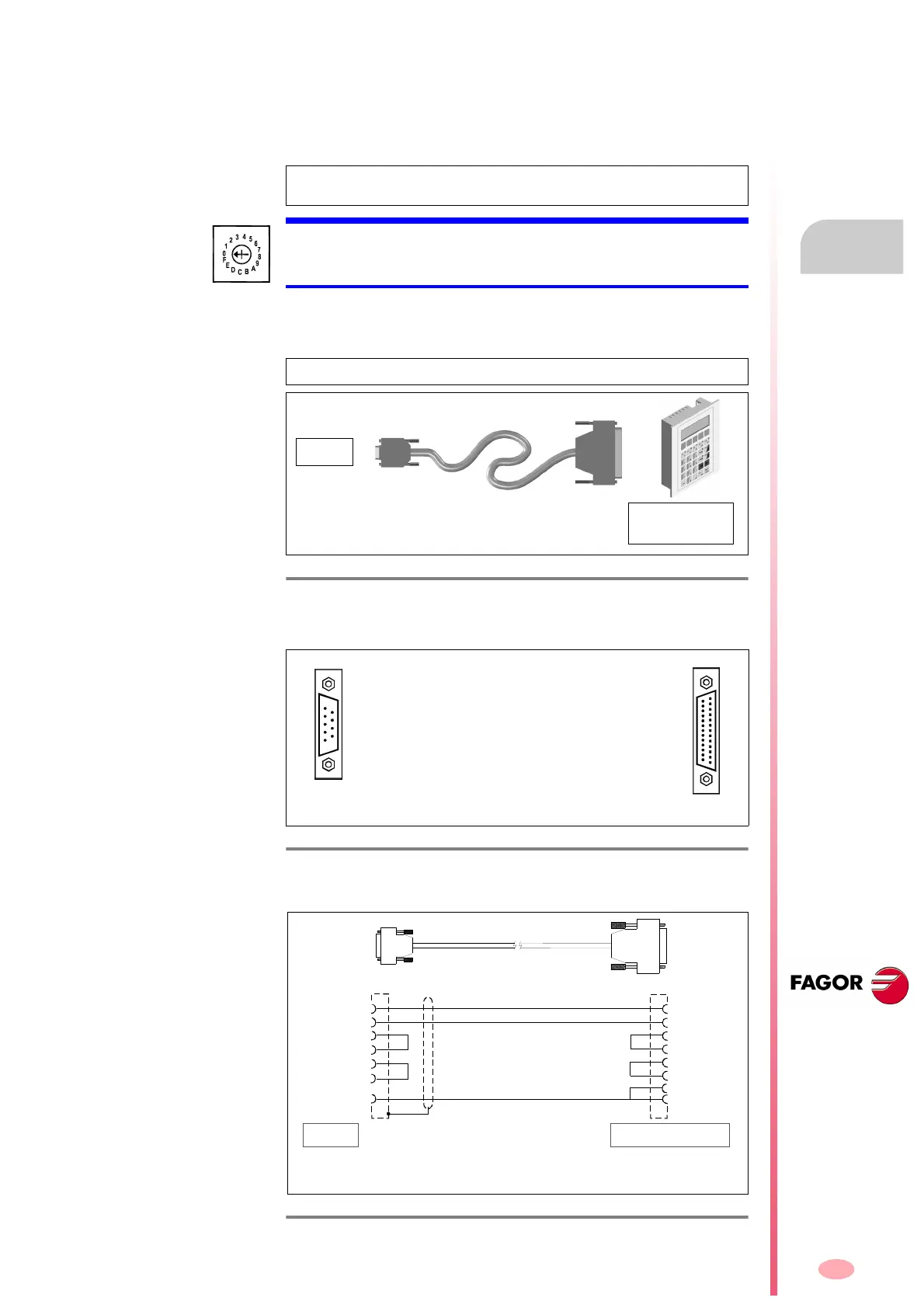
RS-232 serial line cable between a VT and a drive
Once the project has been transferred from the PC to the VT (ESA), the
video terminal may be connected to a single drive, hence establishing
communication via the MSP serial port of the VT and the drive's RS-232
serial port.
It is now possible to handle and control from the Video Terminal the pro-
cess application by communicating with the connected drive. The connec-
tion cable to be used is described next.
The connection cable has the following connectors at its ends:
The connection is:
NOTE. When mentioning a drive, it means any model of the FAGOR
catalog, i.e. AXD, SPD, ACD, SCD, MMC and CMC models.
MANDATORY. The RS-232 serial line can only be used between the ESA
VT and a single drive. The arrow of the drive's node selecting rotary
switch (Node_Select) must be pointing at 0.
NOTE. The adapter RS232/RS422 BE is not required in any case.
F. H7/17
RS-232 serial line connection between the VT from ESA and a drive
(without adapter).
F. H7/18
D.
Connector of the RS-232 cable for direct connection to the drive.
B. Connector of the RS-232 cable for direct connection to the VT from ESA.
F. H7/19
RS-232 connection between a VT and a drive (without adapter).
9-pin Sub-D,
type female
connector
DRIVE
25-pin Sub-D,
type male
connector
to the VT panel
(ESA)
RS-232 cable
D
to drive
(Sub-D, F9)
to the VT panel (ESA)
(Sub-D, M25)
B
These two connectors are at both ends of the RS-232 cable.
8
6
4
3
2
5
Pin
4
15
3
2
5
Pin
CTS
DSR
DTR
TxD
RxD
RTS
Signal
CHASSIS
CTS
TRS
RxD
TxD
GND
Signal
18
25
7
7
Maximum length: 15 meters
To drive
To the VT panel (ESA)
Sub-D, F9
Sub-D, M25
D
B
RS-232 cable
D.
Note that the pairs of pins 4-6 and 7-8 must be jumpered.
B. Note that the pairs of pins 4-5, 7-25 and 15-18 must be jumpered.