Installation
INSTALLATION
Connection between modules
8.
279
DDS
HARDWARE
Ref.1310
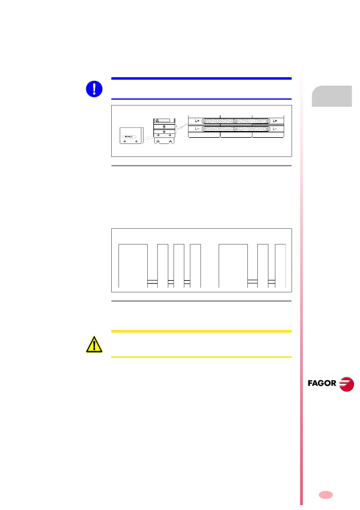
8.4 Connection between modules
Power bus connection
The power bus is connected through the terminals hidden under the cover
at the bottom of each module. To do this, use 2 of the 3 plates and the
washers and nuts supplied with each module.
The tightening torque must be between 2.3
2.8 Nm.
The power supply module must provide the power needed by all the
drives connected to it. If this power exceeds the maximum value that the
power supply can provide, two power supplies will be required.
Assign to each of them the supply of a separate group of drives.
MANDATORY. All the modules must be tightly joined to each other guaran-
teeing a good electrical contact.
F. H8/7
Power bus connection.
F. H8/8
If two power supplies are needed, they must be installed in separate
groups.
DISCHARGE TIME>4Min
HIGH VOLTAGE
DANGER
POWER
SUPPLY
HIGHEST POWER
DRIVE MODULE
DRIVE
MODULE
(A) System
(B) System
X axis drive
Y axis drive
Z axis drive
Power
Supply
(A)
W axis drive
Spindle drive
Power
Supply
(B)
WARNING. The power buses of different power supply modules must nev-
er be connected in parallel. Always make separate groups, connecting
each power supply to a different group of drives.