Installation
INSTALLATION
Connection of the control and communications signals
8.
301
DDS
HARDWARE
Ref.1310
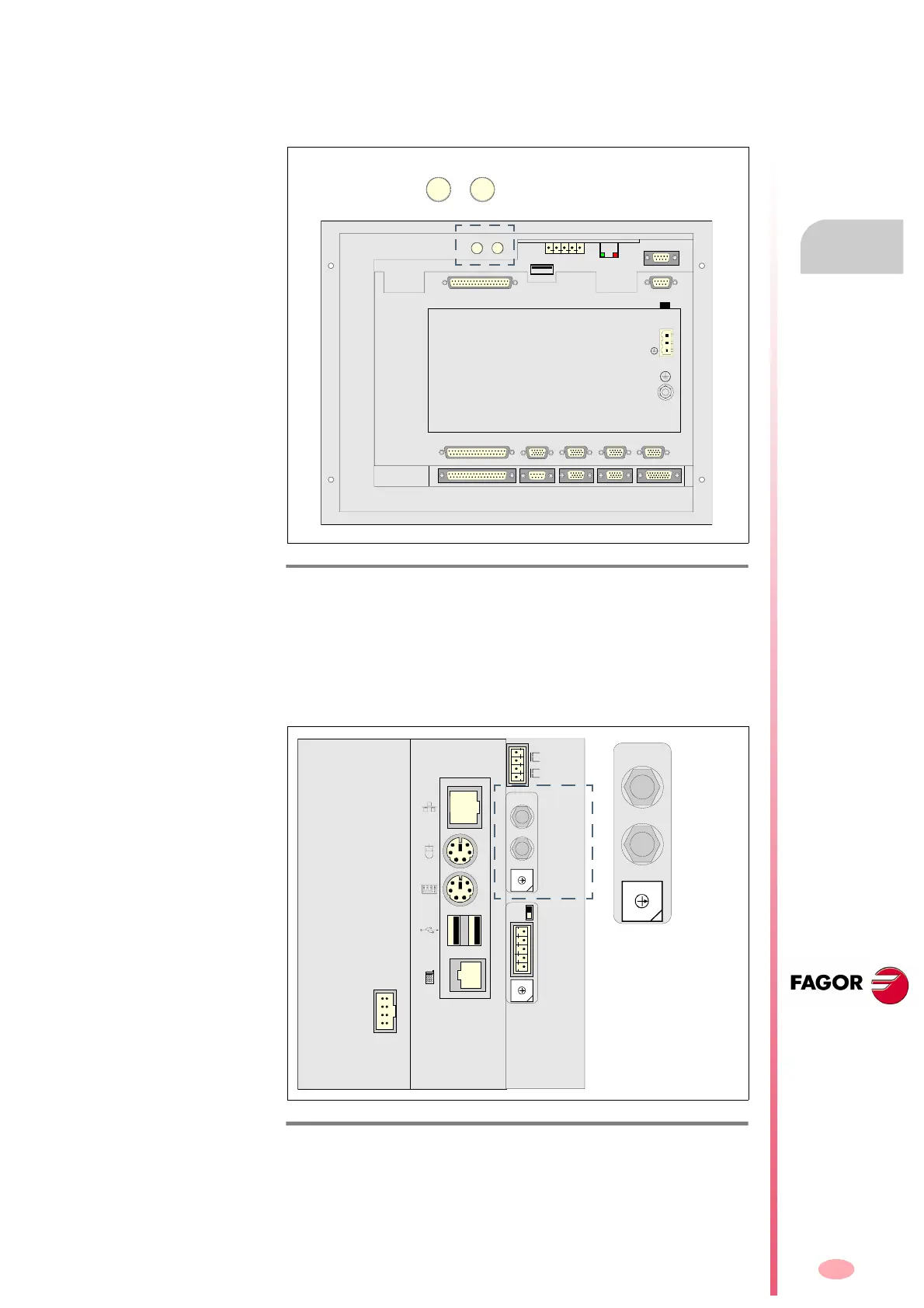
SERCOS connection with a FAGOR 8055i CNC
The SERCOS connection of the FAGOR 8055i CNC will be made through
the SERCOS DRIVES connector on the top rear of the module. See fig-
ure:
For further information, see the installation manuals of the FAGOR 8055i
CNC.
SERCOS connection with a FAGOR 8070 CNC
The FAGOR 8070 CNC is connected to the drives via SERCOS through
the X2 connector located on the right side of the module. See figure:
For further information, see the installation manual of the 8070 CNC.
F. H8/31
SERCOS connector of the FAGOR 8055i CNC.
F. H8/32
SERCOS connector of the FAGOR 8070 CNC.
OUT
IN
X7
X1
X8
X9
X2
X10
X3
X11
X4
X12
X5
X13
X6
+24V
0V
4
0
F
E
D
C
B
A
9
8
7
6
5
3
2
1
1
0
4
0
F
E
D
C
B
A
9
8
7
6
5
3
2
1
X3
X2
X1
ADDRESS
LT
CAN L
SHIELD
CAN H
SHIELD
ISO GND
IN
OUT
ADDRESS
X4
TEC
4
0
F
E
D
C
B
A
9
8
7
6
5
3
2
1
IN
OUT
ADDRESS