Installation
INSTALLATION
Connection of the control and communications signals
8.
303
DDS
HARDWARE
Ref.1310
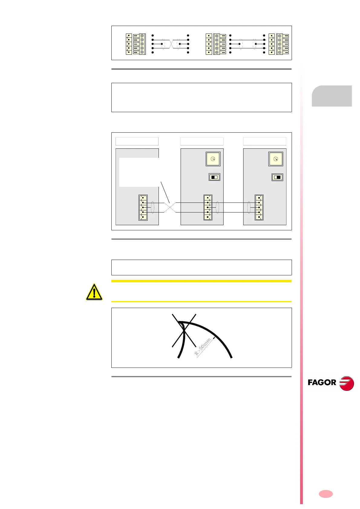
Making all these connections will conclude the connection process. See fig-
ure.
F. H8/33
CAN cable to connect a CNC and two drives.
NOTE. Note that the connectors of the intermediate modules (when con-
necting several drives in the bus) receive two wires, in each pin of the
CAN connector, coming from each adjacent module. The connectors of
the modules at either end only receive one.
F. H8/34
General connection diagram for the CAN bus between the drives and the
master device (CNC, etc.). CAN cable connection.
NOTE. No more than six drive modules (axes + spindles) can be connect-
ed in the CAN bus.
ISO GND
CAN L
SHIELD
CAN H
SHIELD
1
2
3
4
5
5
4
3
2
1
Pin Pin
SHIELD
CAN H
SHIELD
CAN L
ISO GND
5
4
3
2
1
Pin Pin
5
4
3
2
1
C
D
E
F
0
B
A
9
8
1
7
2
6
3
5
4
ADDRESS=1
LINE TERM=0
01
SHIELD
CAN H
SHIELD
CAN L
ISO GND
DRIVE MODULE 1
C
D
E
F
0
B
A
9
8
1
7
2
6
3
5
4
ADDRESS=2
LINE TERM=1
01
SHIELD
CAN H
SHIELD
CAN L
ISO GND
DRIVE MODULE 2
ISO GND
CAN L
SHIELD
CAN H
SHIELD
CNC
11
1
Pay attention to
this wire crossing
when connecting
the cables.
WARNING. The bending radius of the CAN cable must always be more
than 50 mm.
F. H8/35
Minimum bending radius of the CAN cable.