Installation
312
8.
INSTALLATION
Connection of the control and communications signals
304
DDS
HARDWARE
Ref.1310
Line terminating resistor (RT)
After connecting the modules, make sure that the external elements con-
nected to the bus have their terminating resistor RT activated.
The CNC (or the ESA panel), located at the end of the bus always has the
line terminating resistor activated. See figure
F. H8/32.
Transmission speed selection
From version 07.02, 08.01 and newer, the drive may have a CAN card ca-
pable of transmitting data at 1 MB, 800 kBd or 500 kBd.
In this data transmission, each drive can receive and transmit 4 IDns
(CAN identifiers) or 4 Words (64 bits) through the fast channel.
The communication speed between all the drives being governed by the
CNC in the CAN bus is selected by hardware using the “boot” button on
top of the CANcard connector. See figure
F. H8/36.
The parameter associated with the communication speed selection of the
CAN bus is QP11 and every time a speed is selected, this parameter is as-
sociated the corresponding value. See table
T. H8 /5 that shows the possi-
ble baudrate values that will be shown on the drive display. Chapter 12 of
the “dds-software” manual explains the meaning of parameter QP11.
Change of transmission speed
In an initial state (0 state), the display shows certain information that lacks
interest for the operator, except the software version, errors and warnings if
there are any. Keeping the “boot” button pressed for 3 seconds (long push)
it switches to a new state (state 1) that is used for selecting the communica-
tion speed and the display shows the speed currently selected.
In this state 1, every time this button is pressed for less than 0.8 seconds
(short push), the display shows the next communication speed value that
may be selected. Hence, apply several short pushes until the desired
speed is displayed.
NOTE. The RT switch (located under the CAN connector) of the last drive
(usually the one farthest away from the CNC) must be activated (position
1
switch down) and the rest of the drives connected to the bus must be
deactivated (position 0
switch up).
NOTE. This card is not compatible with drive software versions older
than 07.02. See chapter
13. COMPATIBILITY.
NOTE. Consequently, the serial connection will no longer be necessary
to select the transmission speed.
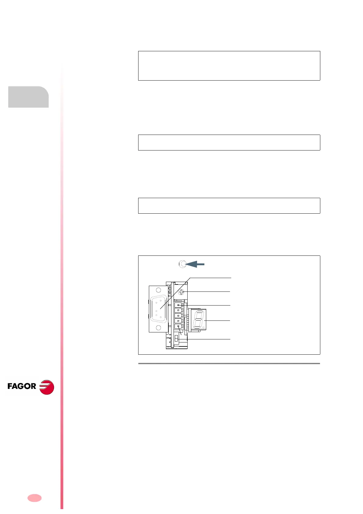
F. H8/36
Location of the “BOOT” button at the drive.
Node selector
“BOOT” BUTTON
X5
Status display
X6
1
1
9
CAN connector
Line terminating resistor
activating switch
RS-232 line connector