Installation
312
8.
INSTALLATION
Connection of the control and communications signals
306
DDS
HARDWARE
Ref.1310
Values that may be assigned to the transmission speed
The possible values, supported by the hardware, that may be selected to
set the transmission speed are:
See the values that will be assigned to their associated parameter QP11 in
chapter
12. PARAMETERS, VARIABLES AND COMMANDS of the “dds-
software” manual.
CAN connection with an ESA video terminal
The CAN connection of the ESA terminal with FAGOR drives is made
through the connector located at the bottom of the VT module. See figure.
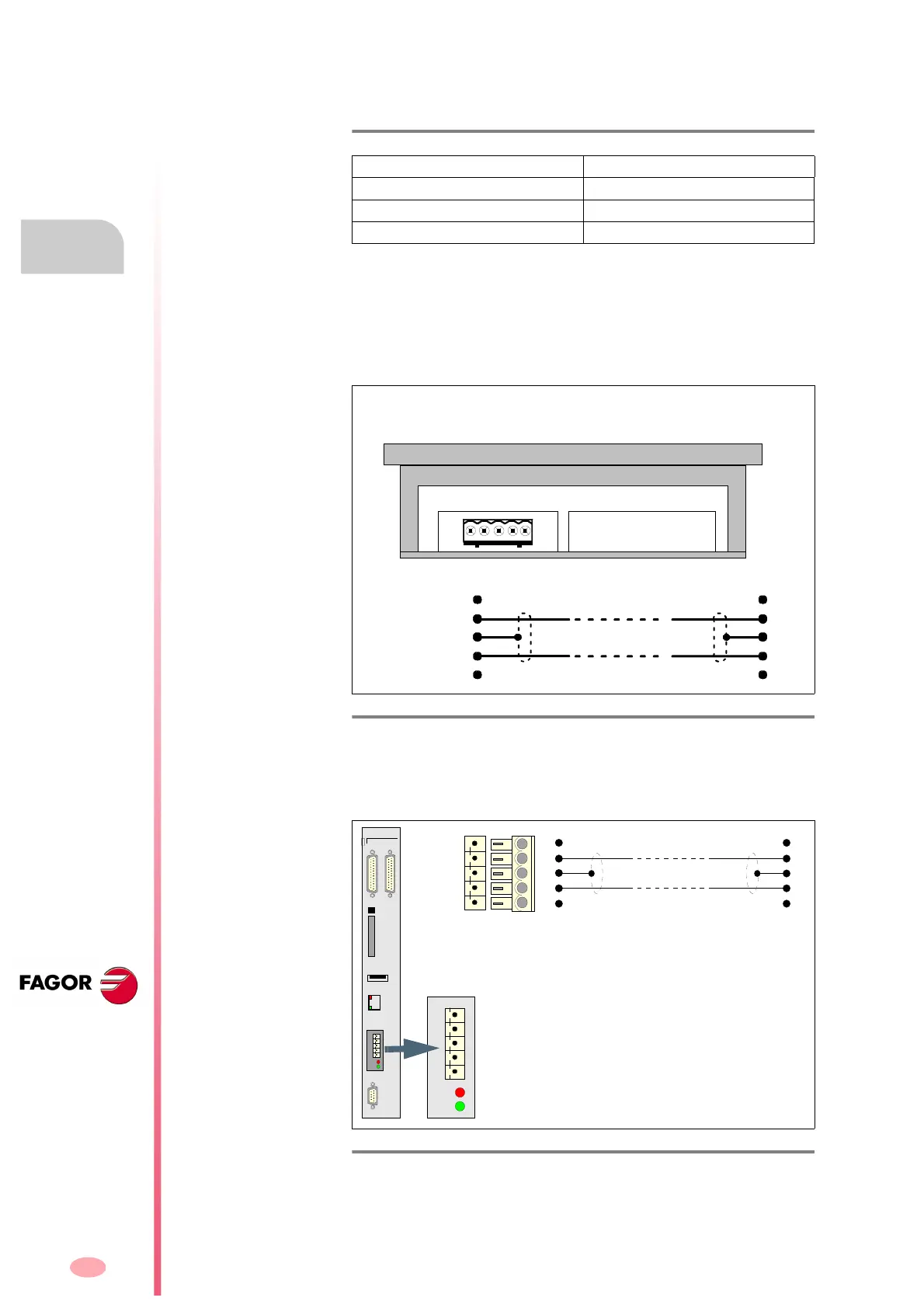
CAN connection with a FAGOR 8055 CNC
The FAGOR 8055 CNC is connected to the drives via CAN through con-
nector COM1 located on the front panel of the CPU module. See figure:
For further information, see the installation manual of the FAGOR 8055
CNC.
T. H8/5 Transmission speed with CAN interface. Display at the drive.
Status display Transmission speed (rate)
1.
1 MBd
8 800 kBd
5 500 kBd
F. H8/38
CAN connector of the ESA Video terminal.
F. H8/39
CAN connector of the FAGOR 8055 CNC.
15 234
CAN L
SHIELD
CAN H
SHIELD
ISO GND
Pin Pin
5
4
3
2
1
5
4
3
2
1
Brown
White
Shield
BOTTOM VIEW
ESA PANEL (VT 150W)
CPU
X1 X2
CMPCT
FLASH
ETH
COM1
X3
USB
Error
Status
Error
Status
ISO GND
CAN L
SHIELD
CAN H
SHIELD
CAN
ISO GND
CAN L
SHIELD
CAN H
SHIELD
1
2
3
4
5
1
2
3
4
5
Pin Pin