EasyManuals Logo

Fagor DDS User Manual

Fagor DDS
386 pages
To Next Page IconTo Next Page
To Previous Page IconTo Previous Page
Page #307 background imageLoading...
Page #307 background image
Installation
INSTALLATION
Connection of the control and communications signals
8.
307
DDS
HARDWARE
Ref.1310
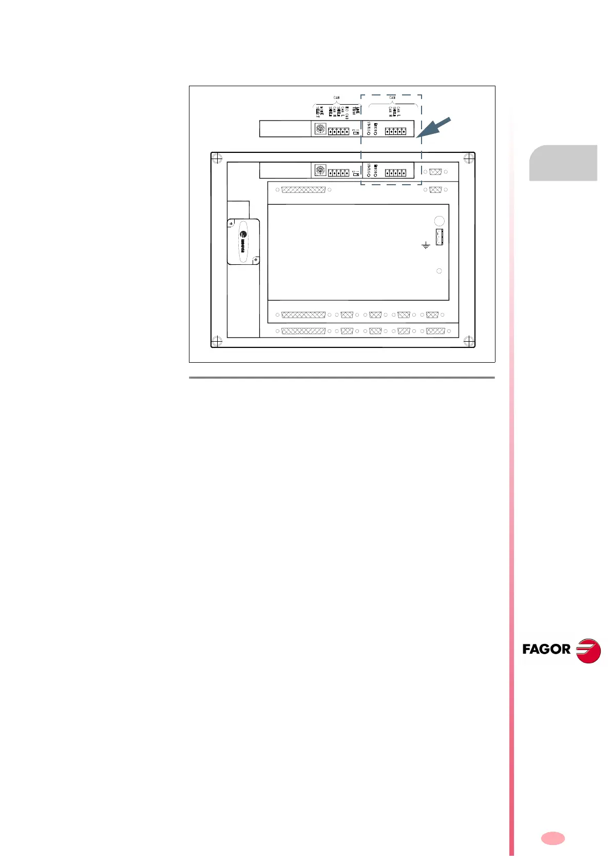
CAN connection with a FAGOR 8055i CNC
The CAN connection of the FAGOR 8055i CNC will be made through the
CAN DRIVES connector on the top rear of the module. See figure:
For further information, see the installation manual of the FAGOR 8055i
CNC.
F. H8/40
CAN connector of the FAGOR 8055i CNC.
X9 X10 X11 X12 X13
X2 X4X3 X6X5
X7
X1
X8
+24V
0V
1
CAN DRIVESCAN I/Os

Other manuals for Fagor DDS

Questions and Answers:

Question and Answer IconNeed help?

Do you have a question about the Fagor DDS and is the answer not in the manual?

Fagor DDS Specifications

General IconGeneral
BrandFagor
ModelDDS
CategoryServo Drives
LanguageEnglish

Related product manuals