Connection diagrams
354
10.
CONNECTION DIAGRAMS
AXD modular drive with FKM synchronous axis servo motor
328
DDS
HARDWARE
Ref.1310
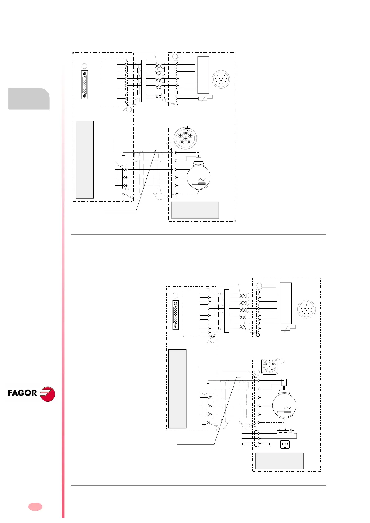
10.2 AXD modular drive with FKM synchronous axis servo motor
10.3 AXD modular drive with FXM synchronous axis servo motor
F. H10/2
Connection of an AXD modular drive with an FKM synchronous axis servo motor with encoder E3.
F. H10/3
Connection of an AXD modular drive with an FXM synchronous axis servo motor with encoder E1.
M
3
MPC- 4x...(mm
2
)+2x1
U
V
W
6
5
3
2
4
1
X1
(Phoenix, 7.6 mm, M3)
U
V
W
Cable without connectors
MC-20/6
socket
+24 V DC
9
1
26
19
(HD,
Sub-D,
F26)
X4
(HD, Sub-D, M26)
X4
(with brake)
EEC-SP 5/10/15/20/25/30/35/40/45/50
Length in meters; including connectors
Ready made cable
Shielded by pairs of cables and overall shield.
The shields of twister pairs must be connected to each other and only at
the drive end joined to the common pin of the chassis (pin 26). The overall
screen must be connected to the connector housing at the drive end and
to the metallic housing and to pin 9 of the connector at the motor end.
The housing of the 26-pin connector must be conductive (metallic).
MC-20/6
base
Holding brake (option)
PTC
EOC-12
Blue
Black
Green
Brown
Grey
Purple
White
Red
20
19
11
2
10
1
21
22
10
2
6
5
1
8
3
4
26
25
12
REFCOS
SIN
REFSIN
+485
-485
GND
+8 VDC
COS
7
23
X2
Yellow
Black
CHASSIS
SIN
REFSIN
+485
GND
+8 VDC
KTY84 -
+t°
E0C-12
1
2
3
4
11
1012
7
8
6
5
9
Front View
KTY-84
KTY84 +
KTY84 +
KTY84 -
Cable 3x2x0.14+4x0.14+2x0.5
COS
REFCOS
- 485
9
Axis Motor
FKM...E3...
E3 SINCOS SINUSOIDAL
ENCODER
4
5
1
6
2
3
24 V Released
0 V Holding
Digital Axis Modular Drive
AXD 1.25-A1-1
Connection diagram of an AXD
modular drive with an FKM syn-
chronous axis motor that has an
encoder E3.
M
3
Holding Brake (Option)
MPC- 4x...(mm
2
)+2x1
U
V
W
C
F
D
B
E
A
+24 V DC
9
1
26
19
(HD,
Sub-D,
F26)
X4
X1
(Phoenix, 7.6 mm, M3)
24 V Released
0 V Holding
E
D
A
C
B
F
X1
U
V
W
Cable without connectors
220 V AC
50/60 Hz
1
2
3
12
3
Digital Axis Modular Drive
AXD 1.25-A1-1
Axis Motor
FXM...E1...
MC-23 OR
MC-46 base
MC-23 OR
MC-46 socket
Electric Fan (Option)
Shielded by pairs of cables and overall shield.
The shields of twister pairs must be connected to each other and only at the
drive end joined to the common pin of the chassis (pin 26).
The overall screen must be connected to the connector housing at the drive
end and to the metallic housing and to pin 9 of the connector at the motor end.
The housing of the 26-pin connector must be conductive (metallic).
PTC
EOC-12
(HD, Sub-D, M26)
X4
Blue
Black
Green
Brown
Grey
Purple
White
Red
20
19
11
2
10
1
21
22
10
2
6
5
1
8
3
4
26
25
12
REFCOS
SIN
REFSIN
+485
-485
GND
+8 VDC
COS
7
23
X2
Yellow
Black
E1 SINCODER STEGMANN
SNS 50 ENCODER
CHASSIS
SIN
REFSIN
+485
GND
+ 8 VDC
TEMP
+t°
E0C-12
1
2
3
4
11
1012
7
8
6
5
9
Front view
TEMP
TEMP
TEMP
Cable 3x2x0.14+4x0.14+2x0.5
COS
REFCOS
- 485
9
EEC-SP 5/10/15/20/25/30/35/40/45/50
Length in meters; including connectors
Ready made cable
Connection diagram of an AXD
modular drive with an FXM syn-
chronous axis motor that has an
encoder E1.