Connection diagrams
CONNECTION DIAGRAMS
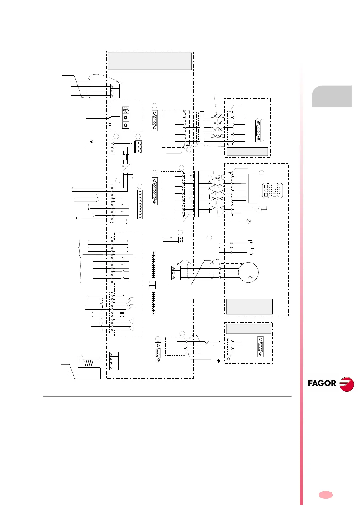
SCD compact drive with FM7 asynchronous spindle motor
10.
329
DDS
HARDWARE
Ref.1310
10.4 SCD compact drive with FM7 asynchronous spindle motor
F. H1 0/4
Connection of an SCD compact drive with an FM7 asynchronous spindle motor with TTL encoder.
Ready Made Cable
EEC- FM7S 3/5/10/15/20/25/30/35/40/45/50
Length in meters;
including connectors
X2
IN
OUT
X2
1
10
(Phoenix, 5.08 mm)
IN
OUT
NODE
SELECT
4
0
8
7
6
3
5
4
8
2
1
SPEED ENABLE
DRIVE ENABLE
DR. O.K.
9
10
PROG. OUT
ERROR RESET
+24 V DC
0 V.
Ri
Re
L+
External Ballast
ER+TH-24/750
X1
3
(Phoenix,
7.62 mm)
1
2
3
1
X1
L1
L2
1 A
(T) Fuses
May be connected
in any order.
2 x 400-460 V AC
Internal
use.
110 mA maximum
OP5
5
4
3
2
1
10
9
8
7
6
11
-15 V
+15 V
5
4
3
2
1
9
8
7
6
+15 V DC
-15 V DC
13
12
11
10
A1 Board
P2
P1
Programmable
Inputs (24 V DC)
Programmable
Outputs
(24 V - 1 A)
IN-1
IN-2
IN-3
IN-4
OUT-1
OUT-2
OUT-3
OUT-4
Analog Output 1
(-)
(+)
IV2
IV1
OP2
OP1
(-)
(+)
Analog Output 2
(-)
(+)
(-)
(+)
OP4
OP3
OP13
OP10
IP10
IP13
OP12
OP11
IP11
IP12
OV2
OV1
1
2
3
4
A
/A
B
/B
5
6
7
8
Io
/Io
11
0 V
(HD,Sub-D,F15)
Reserv.
Reserv.
1
5
11
15
(HD,
Sub-D,
M15)
2
3
RxD
TxD
Serial Line
Interface
Board
(Sub-D, F9)
1
5
6
9
(Sub-D, F9)
X5
1
5
6
9
(Sub-D, M9)
X5
RxD
TxD
2
3
1
2
3
4
5
6
7
8
11
(Sub-D, M15)
MPC- 4x...
M
3
U1
V1
W1
X3
Electric Fan
400 V AC
50/60 Hz
Cable without connectors
(Sub-D, M9)
NTC
MLR-12
(HD, Sub-D, M26)
X4
X4
9
1
26
19
(HD,
Sub-D,
F26)
Green
Blue
Red
Purple
Grey
Yellow
White
Brown
11
2
10
1
25
24
21
22
7
5
4
3
2
1
11
12
26
3
8
GND
COS
REFCOS
SIN
REFSIN
Io
TEMP
TEMP
REF Io
6
12
X2
Black
Black
10
Front View
ENCODER TTL
Green
Yellow
Blue
Purple
Grey
Pink
Brown
White
Black
1
13
1
11
P2
P1
(Phoenix, 3.5 mm)
(Phoenix, 3.5 mm)
Analog Input 2
Analog Input 1
Z1
Z2
Z3
L2
L1
L3
CHASSIS
SS (shield)
Motor ground
screw
Yellow-Green
12 11 10 9
8765
4321
+5 V
0V
PA
*PA
PB
*PB
PC
*PC
THSA
THSB
POWER MAINS
May be connected
in any order.
400/460 V AC
MPC- 4x...
L-
-t°
V
U
W
Note that phases L1 & L2 are swapped
for proper air flow and motor turning directions
indicated on the outside label
AUXILIARY POWER SUPPLY
Cable 3x2x0.14+4x0.14+2x0.5
Cable 4x2x0.142x0.5
AS1
X7
(Phoenix,
5.08 mm)
AS2
Relay
NC
SL1
X6-DIGITAL I/Os
X7-ANALOG I/Os
X6-DIGITAL I/Os
X7-ANALOG I/Os
EXTERNAL
THERMOSTAT
200°C
TO THE
ELECTRICAL
MANEUVER
2.5 mm²
2.5 A
450 V AC
Tk
Tk
5
1
11
15
(HD,Sub-D,F15)
+5 V
Digital Spindle Compact Drive
SCD 1.25-A ...
SEC-HD 1/3/5/10/15/20/25/30/35
Ready made cable to 8055/55i CNC,
Length in meters; including connectors
CNC 8055/55i
Encoder simulator
option
X3
X3
Spindle Motor
FM7...S...
PC-Computer
R
S
T
Connection diagram of an SCD
compact drive with an FM7 asyn-
chronous spindle motor that has
encoder feedback.