Power supplies
94
2.
POWER SUPPLIES
Regenerative power supplies
58
DDS
HARDWARE
Ref.1310
Power connectors
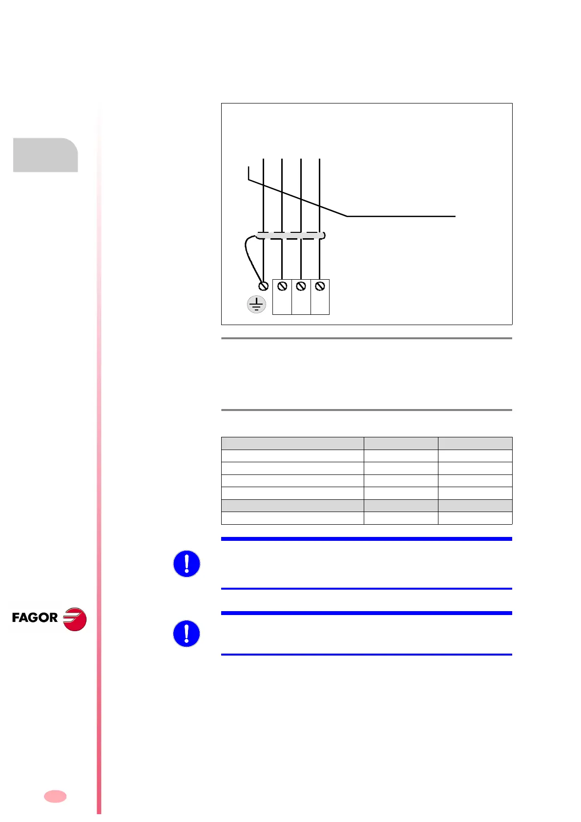
Terminal strip for mains connection
When connecting the power supplies to mains, the phases may be con-
nected in any order.
The ground connection of the cable shield is made from the vertical plate
next to the terminal strip.
The following table shows the values for gap, tightening torque, sections
and other interesting data of the power feed-through terminal blocks:
F. H2/19
Terminal strip for connection to mains.
T. H2/16 Technical data of the feed-through terminal blocks for mains
connection
Connector data XPS-25 XPS-65
Min/max tightening torque (N·m) 2.0/2.3 6/8
Screw thread M5 M6
Min./max. section (mm²) 0.5/16 16/50
Rated current In (A) 76 150
Wire data
Length to strip (mm) 16 24
The RST phases may
be connected in any
sequence
Cable without connectors
MPC-4x ... (mm²
)
FROM MAINS
MANDATORY. As for possible high leak currents, use a protection ground wire
with a cross section of at least 10 mm² (Cu) or 16mm² (Al) or two protection
ground wires with the same cross section as that of the wires connected to
the power supply terminals. Comply with local regulations on grounding.
MANDATORY. The equipment must be protected with fuses on the three-
phase supply lines L1, L2 and L3. Follow the instructions given in chapter
6. POWER LINE CONNECTION of this manual.