Power supplies
POWER SUPPLIES
Regenerative power supplies
2.
59
DDS
HARDWARE
Ref.1310
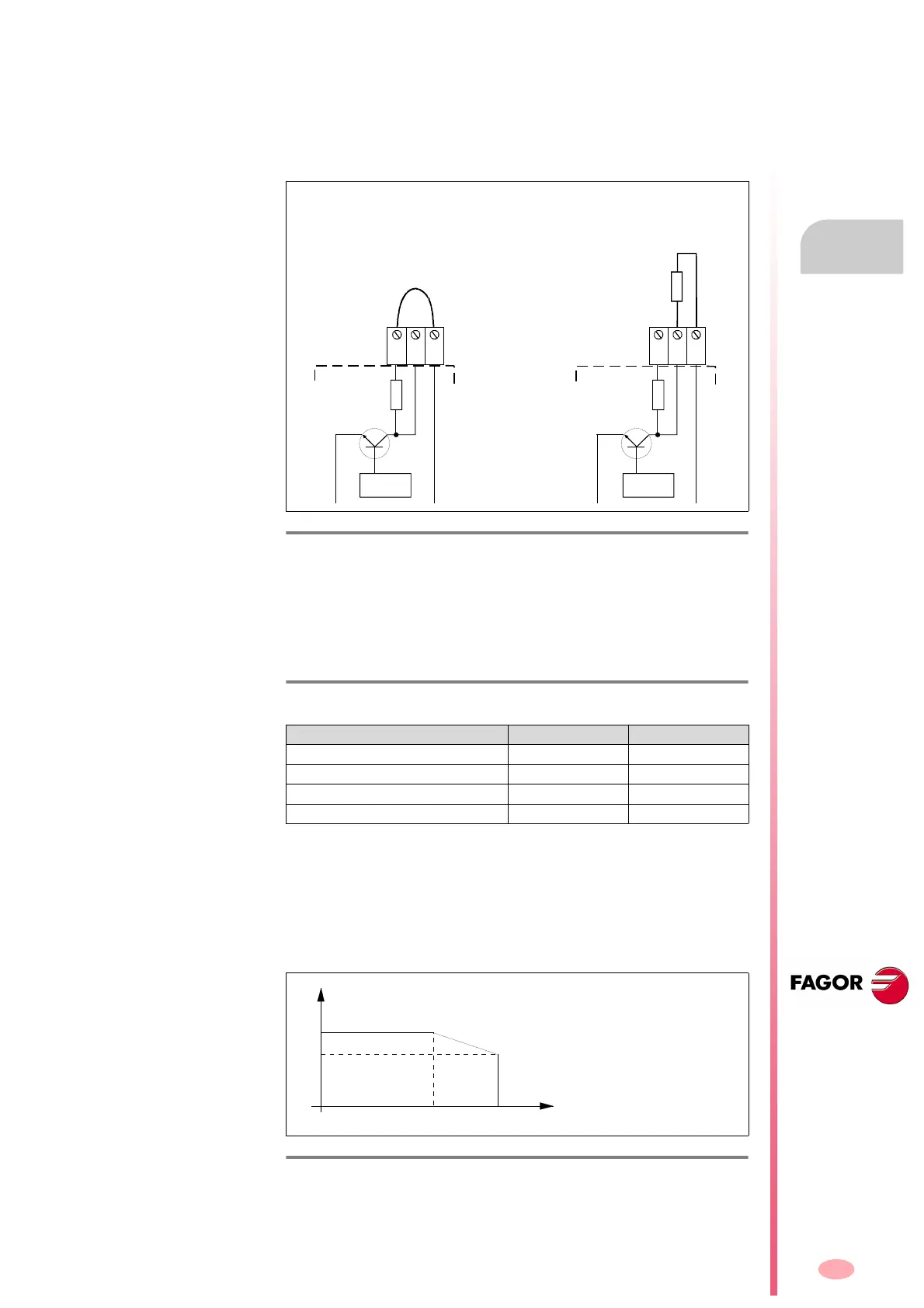
Terminal strip to connect the Ballast resistor
Regenerative power supplies also have a small Ballast Circuit for dissipat-
ing energy in case of an emergency. This emergency is issued when
there is no connection to mains and the Ballast circuit activating voltage is
exceeded. See table T. H2/14 in this chapter. Here are the two possible
configurations:
Removing this jumper between Ri and L+ (factory setting) and not connect-
ing an external resistor between Re and L+ generates error code E215 or
E304 on the display.
The following table shows the values for gap, tightening torque, sections
and other interesting data of the feed-through terminals blocks for connect-
ing the ballast resistor:
These power supplies carry a protection against over-temperature which
triggers error E301 on the display when reaching 105 °C (221 °F).
Derating curves
The power that may be dissipated through the internal ballast resistor lo-
cated inside the power supply XPS-25 depends on the ambient tempera-
ture as determined by the derating curve.
The performance of the internal Ballast resistor of the regenerative power
supply XPS-65 does not suffer at high temperatures.
F. H2/20
Ballast resistor connection configurations.
T. H2/17 Technical data of the feed-through terminal blocks for connect-
ing the ballast resistor.
Connector data XPS-25 XPS-65
Min/max tightening torque (N·m) 0.6/0.8 0.6/0.8
Screw thread M3 M3
Min./max. section (mm²) 0.2/4 0.2/4
Rated current In (A)
32 32
F. H2/21
Derating curve of regenerative power supplies XPS-25.
Configuration of the
internal resistor
Configuration of the
external resistor
L-
L+
L-
L+
XPS-25
XPS-65
XPS-65
XPS-25
CONTROL
Ri Re L+ Ri Re L+
CONTROL
R.int
R.int
R.ext
ER+TH-X/X
ER+TH-18/X+FAN
INTERNAL BALLAST
POWER (W)
XPS-25
600
520
35/95 45/113
°C/°F