Power supplies
POWER SUPPLIES
Regenerative power supplies
2.
61
DDS
HARDWARE
Ref.1310
Remember that the purpose of connecting an auxiliary power supply APS-
24 to the DC bus of a DDS system is to ensure the supply to all the control
circuits of the power supply and of the drive modules connected to the DC
bus in case of a mains power outage in the auxiliary power supply ensuring
a controlled stop of the moving axes instead of braking out of control by fric-
tion.
Bear in mind that although XPS power supplies come with an internal auxil-
iary power supply offering 3 outputs with 24V DC and a total of 8 A, 192 W,
this power may not be enough to feed the control circuits of all the modules
connected or other elements (e.g. a fan). That is why it may be necessary to
also install an APS-24 auxiliary power supply to guarantee all the power
needed.
The APS-24 auxiliary power supply offers 3 outputs with 24 V DC and a total
of 10 A, 240 W.
For further information about the auxiliary module APS-24, see chapter 4.
AUXILIARY MODULES in this manual.
Choke connection terminals
Regenerative power supplies XPS-25 and XPS-65 offer the connection ter-
minals labeled CH1 and CH2 at the bottom of the module for connecting the
choke. See figure F. H2/17 and figure F. H2/18.
This inductive device is a must to limit the current circulating from the power
bus to mains.
FAGOR supplies the choke XPS-25 and choke XPS-65-A for this applica-
tion.
Use cables with the maximum section allowed 16 and 50 mm² y and shorter
than 2 meters (6 feet). They do not have to be shielded.
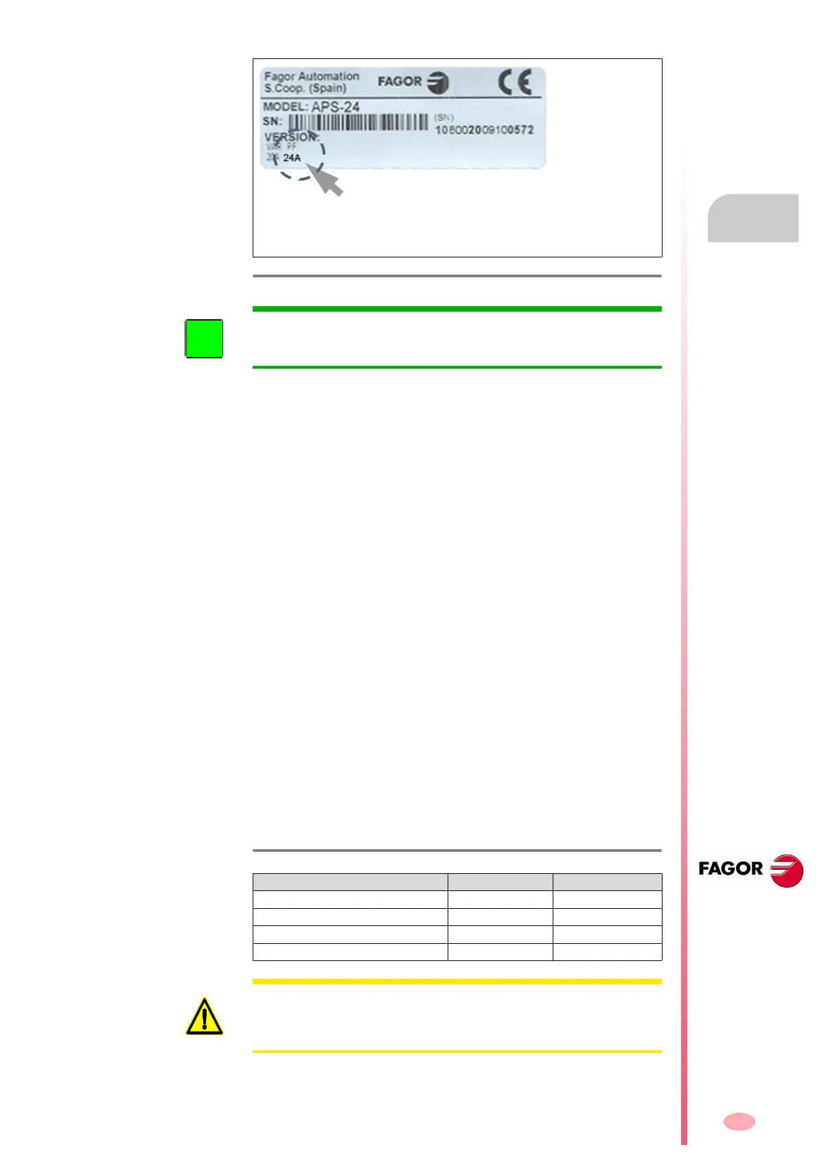
F. H2/22
Version label of the APS-24.
Observe the PF reference on the versions label.
Depending on this reference, it will be possible to con-
nect the APS-24 or not to the DC bus of the DDS system
with XPS regenerative power supplies.
INFORMATION. It will not be necessary to install external protection fuses
in these power lines of the auxiliary power supply. They are already inte-
grated in the power supply itself.
T. H2/18 Data of the feed-through terminal blocks for connecting the choke.
Connector data CHOKE XPS-25 CHOKE XPS-65-A
Min/max tightening torque (N·m) 2.0/2.3 6.0/8.0
Screw thread M5 M6
Min./max. section (mm²) 0.5/16 16/50
Rated current In (A) 76 150
WARNING. The choke is an absolute must for the operation of a regener-
ative power supply. Installing the coil with an inductance other than the
choke recommended in table T. H2/14 may cause severe damage to the
unit.