Power supplies
POWER SUPPLIES
Regenerative power supplies
2.
63
DDS
HARDWARE
Ref.1310
The next table shows the signals and other considerations related to each
pin of connector X2:
X3, X4, X5 and X6 connectors
These connectors belong to the auxiliary power supply integrated into the
main power supplies XPS-25 and XPS-65.
Connector X3 receives power from mains. It admits a voltage between 400
and 460 V AC.
This auxiliary power supply generates 24 V DC and its purpose is to feed
the control circuits of the module itself. Also, it supplies up to 8 A of this dc
voltage through connectors X4, X5 and X6. These three connectors are
identical and offer greater connecting flexibility.
T. H2/20 Description of the pins of connector X2.
1 Error RESET
System error RESET input
(24 V DC; 4.5-7 mA).
2 N. C. Not connected
3GND
0 volts reference for digital inputs.
Error RESET (1) and
System Speed Enable (5).
4 N. C. Not connected
5 System Speed Enable
General system speed enable.
(24 V DC; 4.5-7 mA).
6 System OK
Contact indicating module status.
It opens in case of failure.
Limit 1 A at 24 V.
7 System OK
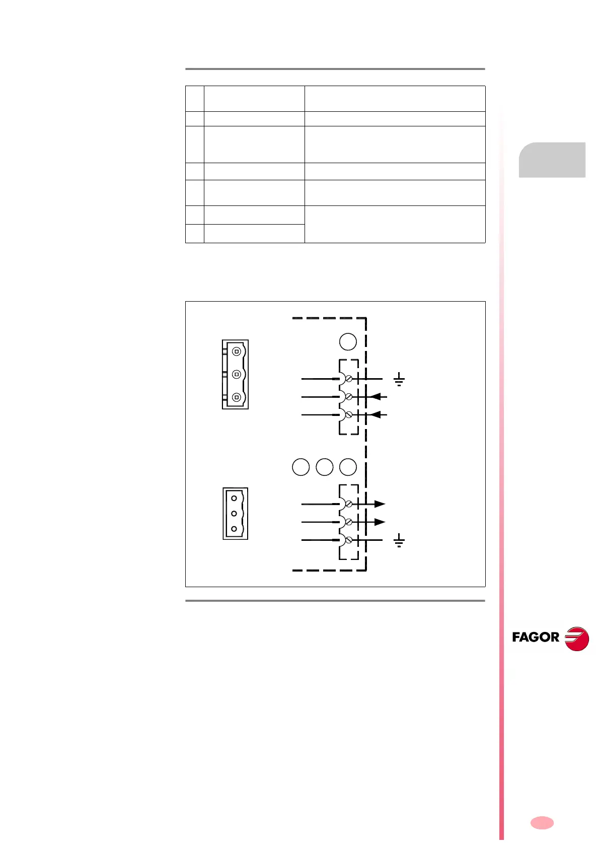
F. H2/25
Connectors X3, X4, X5 and X6 that belong to the auxiliary power supply
integrated into regenerative power supplies XPS-25 and XPS-65.
1
2
X3
XPS-25
XPS-65
3
400-460 VAC
Phoenix
7.62 mm
1
3
Phoenix
5.08 mm
1
2
X6
3
+24 VDC
0 VDC
1
3
X4
X5