Power supplies
POWER SUPPLIES
Regenerative regulated power supplies
2.
87
DDS
HARDWARE
Ref.1310
The following table shows the values for gap, tightening torque, sections
of the screws and other data of the plug-in connector for X3.
X4 connector
This connector may be used to connect the various modules to each oth-
er through the internal bus communicating with each other the power sup-
ply and all the servo drives that make up the DDS system.
A ribbon cable is provided with each module (power supply or drive) for
this connection.
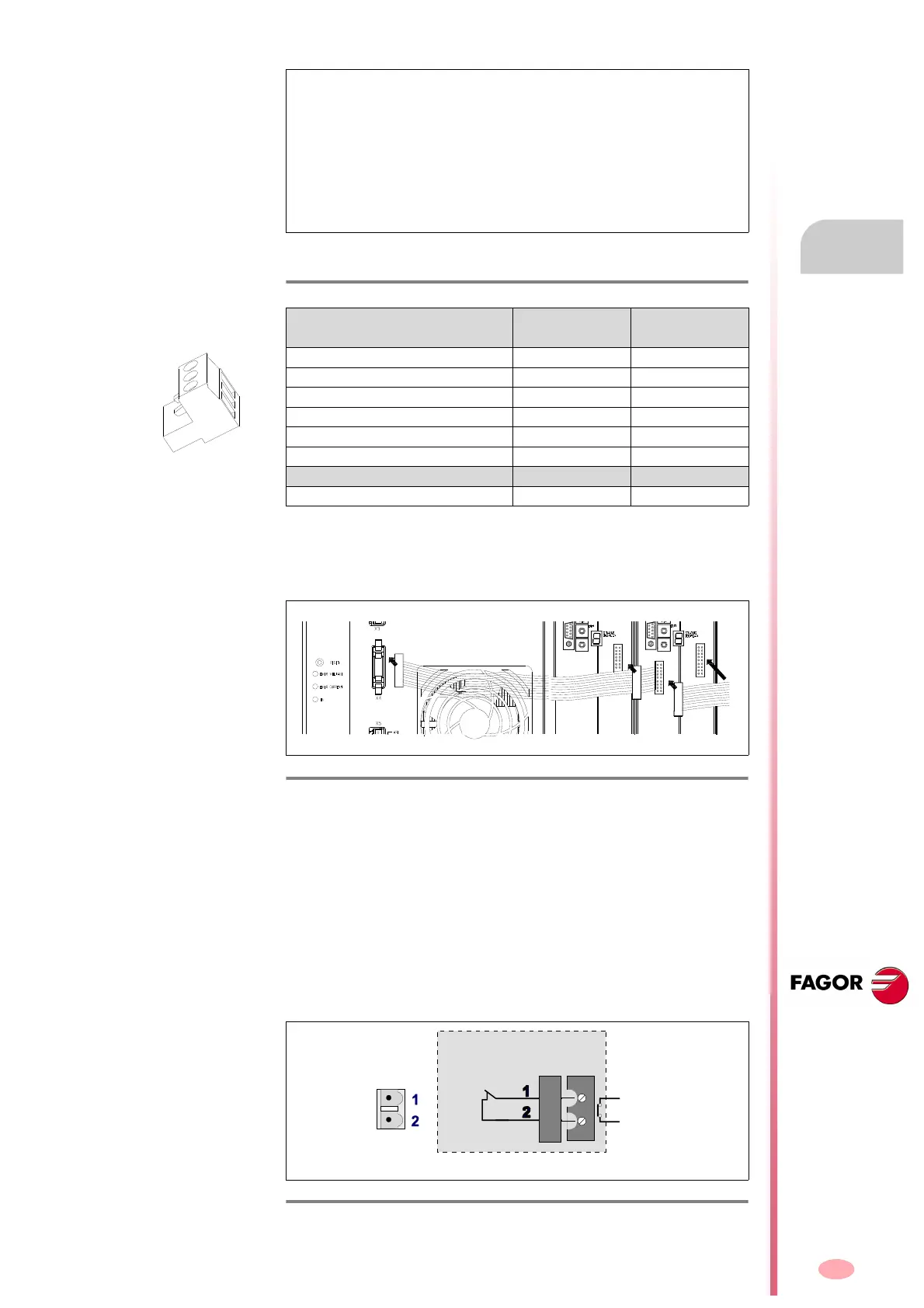
X5 connector
This connector X5 of the RPS power supply is associated with the sec-
ond contact (N.C., Normally Closed) of an internal safety relay (with guid-
ed contacts). The status of the relay (initially closed) will be acknowledged
through its two pins and a CNC, PLC, control panel, etc. will confirm that
the integrated safety relay has actually opened or closed. These two ter-
minals are identified as AS1 and AS2. The opening or closing of this re-
lay depends on whether 24 V DC are present at pin 4 <PWM ENABLE>
of control connector X6.
NOTE. It is important to know that if NS1 (pin 3 de X3) and NS2 (pin 4
de X3) are not short-circuited by the user, the main internal contactor
“LINE CONTACT” will stay open. The power supply will start up, but the
DC BUS will not charge and, therefore, the axes cannot move. The sta-
tus display may show the warning - A315 - indicating that the DC bus
charging time (SoftStart type) has exceeded the maximum set value be-
cause it never gets charged. Therefore, the main internal contactor
“LINE CONTACT” (pins 3 and 4) MUST BE CLOSED for the system
to run.
T. H2/34 Data of the plug-in connector for X3.
Connector data
RPS-80
RPS-75
RPS-45
RPS-20
Nr of poles 4 4
Gap (mm) 5.00 5.00
Min/max tightening torque (N·m) 0.5/0.6 0.5/0.6
Screw thread M3 M3
Min./max. section (mm²) 0.2/2.5 0.2/2.5
Rated current In (A) 12 12
Wire data
Length to strip (mm) 7 7
F. H2/47
Connector X4. Internal bus connection between modules.
F. H2/48
Connector X5. External acknowledgment of the status of the integrated
safety relay.
(Phoenix,
5,00 mm)
X5
AS1
AS2
RPS-