In chart 1,
there is a layer 2 switch without setting VLAN. Any broadcast frame will be
transmitted to the other ports except the send port. For example, a broadcast
information is sent out from port 1 then transmitted to port 2,3and 4.
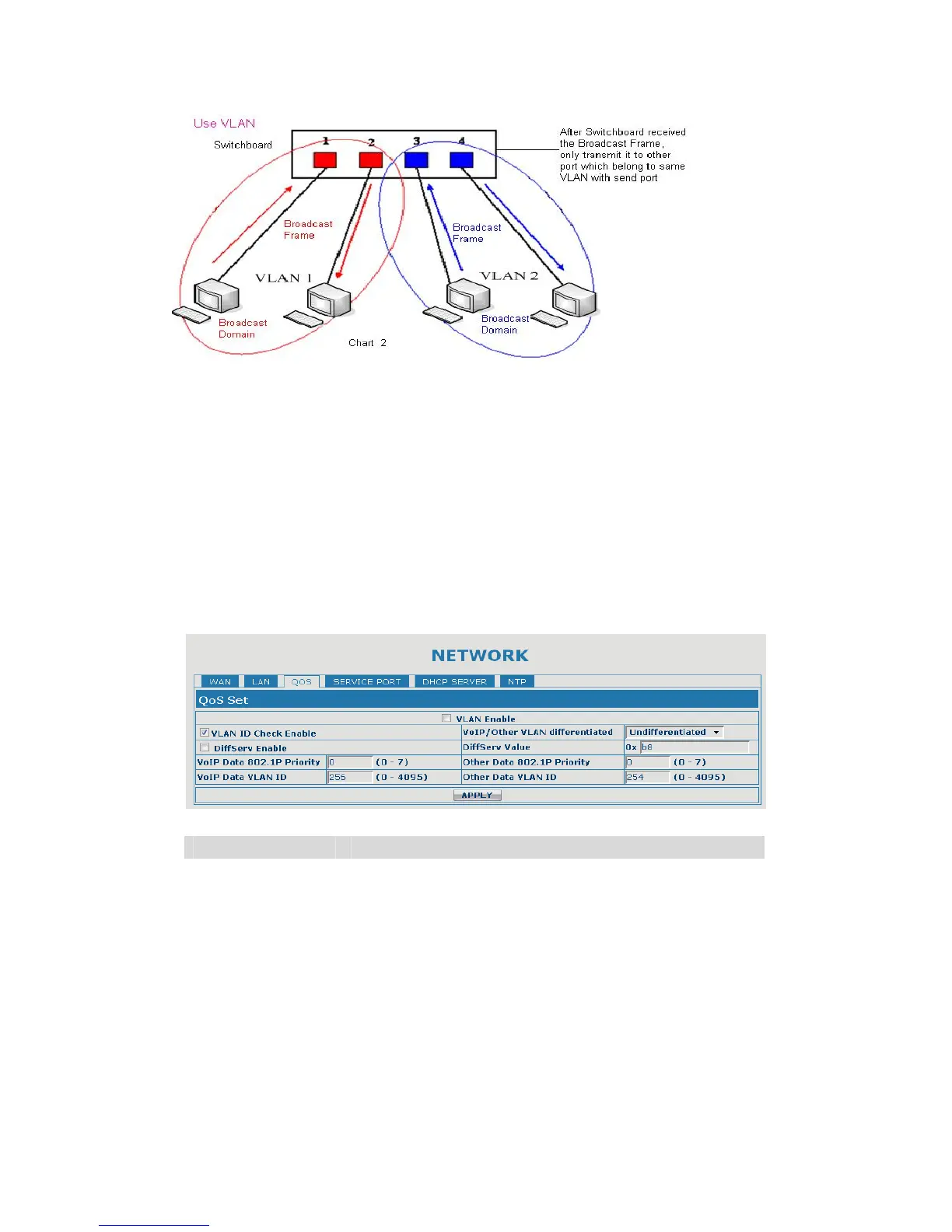
In chart 2, red and blue indicate two different VLANs in the switch, and port 1 and
port 2 belong to red VLAN, port 3 and port 4 belong to blue VLAN. If a broadcast
frame is sent out from port 1, switch will transmit it to port 2, the other port in the
red VLAN and not transmit it to port3 and port 4 in blue VLAN. By this means, VLAN
divide the broadcast domain via restricting the range of broadcast frame transmit
ion.
Note: chart 2 use red and blue to identify the different VLAN, but in practice, VLAN
uses different VLAN IDs to identify.
QoS Configuration
Field name explanation
VLAN Enable Before select it to enable VLAN, you need enable Bridge
mode in LAN config.
VLAN ID Check
Enable
Enable VLAN ID check by selecting it. After enable
VLAN ID check, if VLAN ID of a data package is not the
same with the gateway or a data package do not have
VLAN ID, the data package will be discarded.
Voice/Data VLAN
differentiated
After enable VLAN, system will set packets with
different type of VLAN ID. Undifferentiated means after
using VLAN, both VoIP packets and other data packets
will use the voice VLAN ID; tag differentiated means
after using VLAN, VoIP(signal and voice) packets will