MPC-6000 / MPC-7000 / RND-2 INSTALLATION, OPERATION AND MAINTENANCE MANUAL
33
There are two key-shaped cutouts on the top of the backbox. Make sure the end with the two
key-shaped cutouts is on top when installing the backbox.
Drill the two holes located in the previous step and screw in the top bolts, leaving a small
gap between the wall and each top bolt.
The screw type and length must be able to support the control panel, options and battery set.
You may need a different screw type, depending on the wall material.
Place the backbox over the two top bolts and allow it to slide down over the bolts.
Mark, drill, and install the two bottom bolts in the backbox.
Tighten all four bolts securely against the back wall of the backbox.
The RSE-300 Auxiliary Power Supply or battery enclosure may be mounted immediately
below the main enclosure, close nipple, allowing a minimum of 1 inch in between the
enclosures for clearance between the doors. Keeping the wire run to the control unit short
will keep the voltage drop to a minimum.
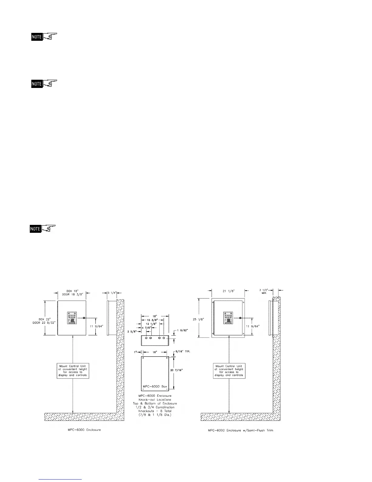
If a semi-flush mount installation is desired, use the SFTK-6(R/B) Semi-flush Trim for the
MPC-6000 / RND-2 and the SFTK-7(R/B) Semi-flush Trim for the MPC-7000. The backbox
can be mounted up to 3 1/2 inches into the wall. Place the semi-flush trim around the
backbox and affix to the wall with four #10 x 3/4 inch wood screws (provided with trim).
You may need a different screw type, depending on the wall material.
For semi-flush installations, if the RSE-300 Auxiliary Power Supply or a battery enclosure is
required, it may be mounted immediately above or below the main enclosure, close nipple,
allowing a minimum of 3 inches in between the enclosures for clearance between the semi-
flush trims. Keeping the wire run to the control unit short will keep the voltage drop to a
minimum.
MPC-6000 and RND-2 Enclosure Mounting Pictures