MPC-6000 / MPC-7000 / RND-2 INSTALLATION, OPERATION AND MAINTENANCE MANUAL
90
APPENDIX-N: DIAGNOSTIC PRINTER
Diagnostic printers are NOT supervised and MUST NOT be installed permanently on the panel
(typically longer than 24 hours). The printers are used strictly for diagnostic purposes only.
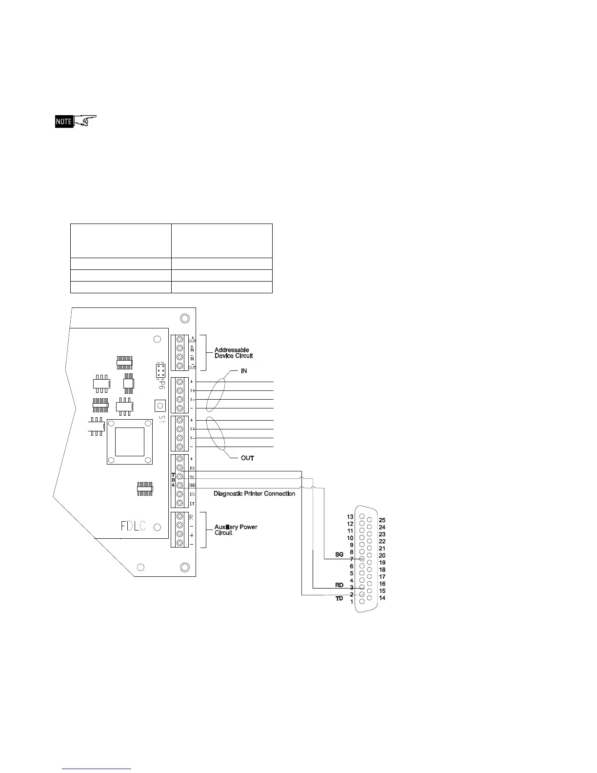
MPC-6000 / MPC-7000 printer connection
Diagnostic printers are connected to the MPC-6000/ -7000 panels through terminal TB4 of its
main board using an RS232 DB25 serial cable (serial cable is not provided). See Figure 1
below.
Following are the pin connections to connect the diagnostic printer:
Main Board
TB4 Terminal
RS232 DB25
(serial printer)
Pin Number
RX 2 – TXD
TX 3 – RXD
GND 7 – SG
Figure 1
DB25 RS232 Diagnostic Printer Connection