MPC-6000 / MPC-7000 / RND-2 INSTALLATION, OPERATION AND MAINTENANCE MANUAL
36
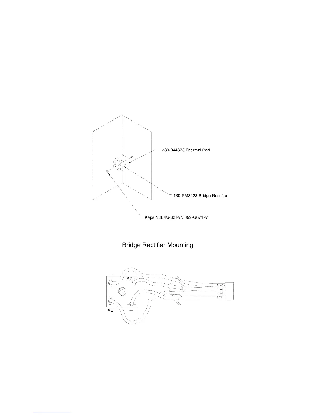
Bridge Rectifier Installation – P/N 130-PM3223
Secure the bridge rectifier (P/N 130-PM3223) to the backbox, placing the thermal pad (P/N
330-944373) between the Bridge Rectifier and the backbox using a provided #6 keps nut
(P/N 899-G67197). See drawing below for details.
Wire Bridge Rectifier to Rectifier Cable Assembly (555-449116). Red wire goes to the plus
(+) connection of Bridge Rectifier and Black wire goes to the minus (-) connection of the
Bridge Rectifier. Gray wires connect to the AC connections of the Bridge Rectifier. Plug
Rectifier Cable Assembly into J4 on the Main Board (P/N MPC(6/7)-MB).