MPC-6000 / MPC-7000 / RND-2 INSTALLATION, OPERATION AND MAINTENANCE MANUAL
47
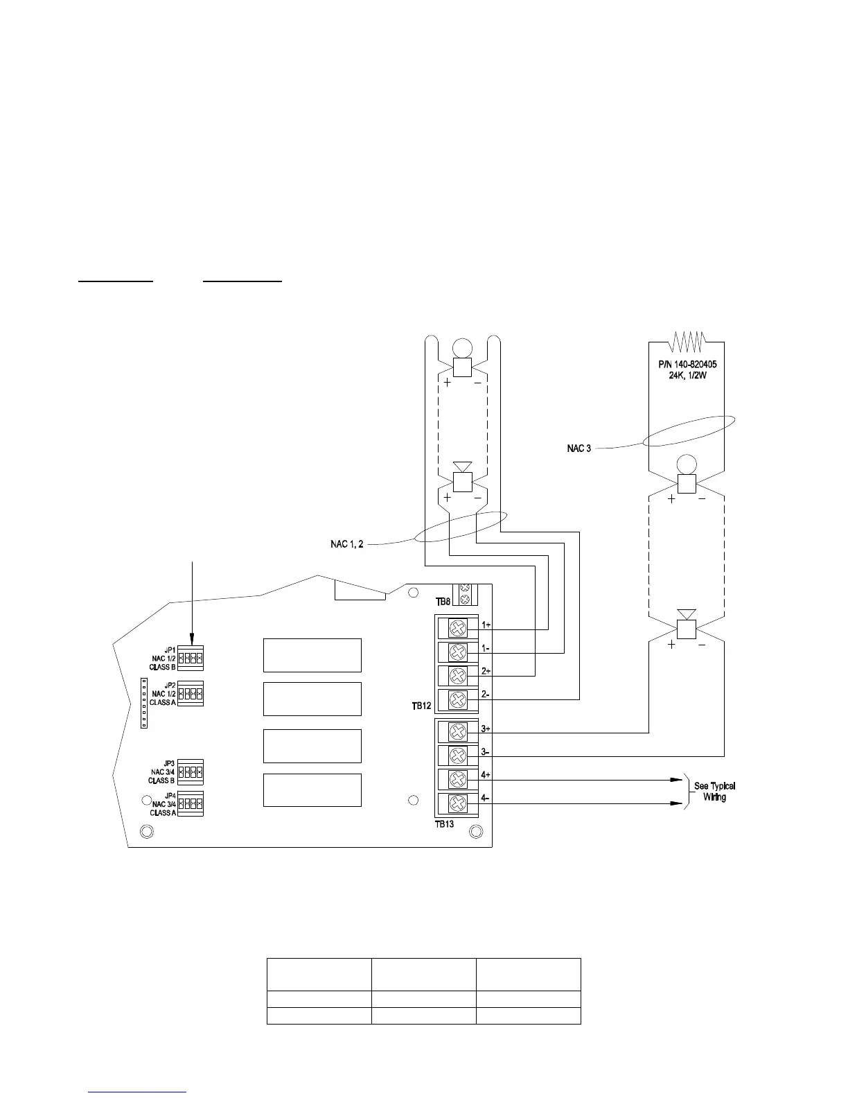
NAC Wiring
At the lower right corner of the main board the terminal blocks TB12 and TB13 are used for the
connection of notification appliances. Four individual NACs marked 1 through 4 are provided
and the polarity shown is when the NAC is activated.
Use the following table to configure the NACs for either Class A or Class B operation by
placing the 8-pin jumper to the proper socket location. This must be configured before system
power up.
NAC #s Class “B”
Operation
Paired Class
“A” Operation
1,2 JP1 JP2
3,4 JP3 JP4
Power Limited
Alarm Voltage: 24V nominal, unfiltered fullwave
rectified (31V max.)
Max. Alarm Current: 1.5A/NAC circuit
Max. Ripple: 16VAC, 120Hz
Maximum Line Resistance @ 24V (nominal),
unfiltered fullwave rectified
Current Draw Line Impedance
1.5A 2Ω
1.0A 3Ω
0.5A 6Ω
Max. Standby Current: 3.4mA
For special application only. Suitable for coded and
non-coded application.
Refer to Appendix B to determine maximum sync
notification appliances allowed per NAC.
NOTE:
The maximum total current for the MPC-6000 NACs is
3.0A and 6.0A with the optional additional
Transformer P/N NPE-1.
The maximum total current for the MPC-7000 NACs is
5.0A and 8.0A with the optional additional
Transformer P/N NPE-1.
Voltages are in RMS values.
Typical
Notification Appliance Circuit
Style Z, Class A
Supervised, Power Limited
See Appendix B for
Compatible Devices
No EOL Device
Typical
Notification Appliance Circuit
Style Y, Class B
Supervised, Power Limited
See Appendix B for
Compatible Devices
See table for
NAC Jumper
Configurations
Polarity Shown
In Activated Condition