87
(MT11 - Gb2012)
RL37D
CP
A1
A1
FP
FP
A
PRS210
Compact
Echos
230V
127V
0
ExhitoExhito
1+1
INTERCOMS *
4+1
VIDEOINTERCOMS
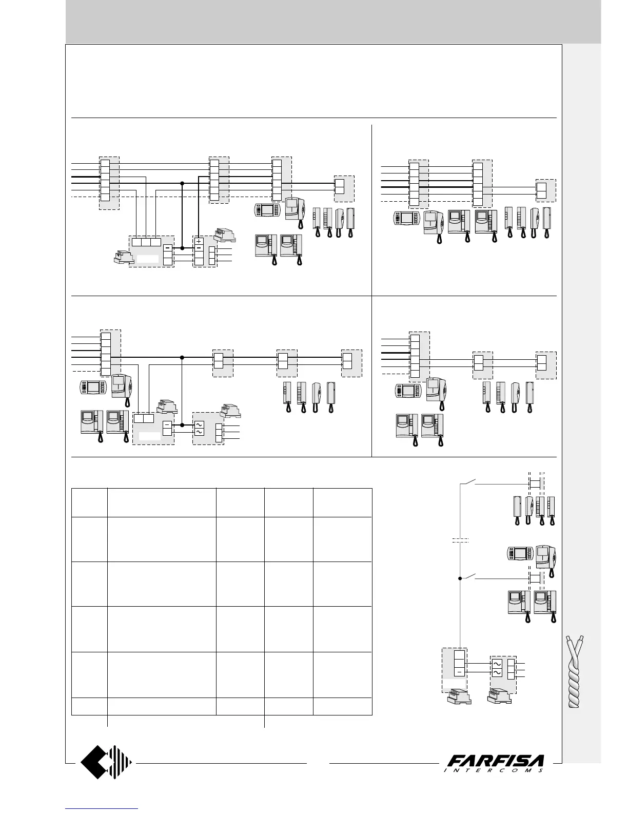
b) Application of 2 videointercoms and 1 inter-
com in parallel
c) Application of 1 videointercom and 3 intercoms in parallel
d) Application of 1 videointercom and 2 inter-
coms in parallel
230V
127V
0
1281
X
Y
H
F
10
4
A
I
A
IV
X
Y
H
F
10
4
3
1
1P
1M
H
RL37D
X
Y
H
F
10
4
VC1 VC2 VC3
CT
Compact
Echos
Exhito
EX321
KM811
PT511E
EX311
Exhito
a) Application of 3 videointercoms and 1 intercom in parallel
Additional diagrams for systems NOT intercommunicating
All videointercom installation diagrams in this technical manual are drawn with only one video intercom for each user. It is possible to “personalise”
the installation by properly matching the applications on the following pages to the basic diagrams. To obtain the requested wiring diagram it is
necessary overlay the desired application diagram on the “basic” diagram in order to cover the existing videointercom (VC1 will replace the
videointercom of the basic diagram). More than one application diagram can be overlaid on a multi-ways diagram.
e) Floor call (for intercom and videointercom sys-
tems)
3
1
3
1
VC1
CT2CT1
X
Y
H
F
10
4
EX321 KM811
PT511E
EX311
Compact
Echos
ExhitoExhito
230V
127V
0
PRS210
A
3
1
3
1
3
1
1P
1M
RL37D
X
Y
H
F
10
4
VC1
CT3CT2CT1
EX321 KM811
PT511E
EX311
Compact
Echos
ExhitoExhito
Diagram Videointercoms + Intercoms Power Supplementary
accessories supplies call module
2 EH9161 + 2 9083 1 EX311
"a" 2 EX3100 + 2 WB3161 1 EX321 1 1281 1 RL37D
2 EX3160 + 2 WB3161 1 KM811
2 KM8111 + 2 WB8111 1 PT511E
1 EH9161 + 1 9083 1 EX311
"b" 1 EX3100 + 1 WB3161 1 EX321
1 EX3160 + 1 WB3161 1 KM811
1 KM8111 + 1 WB8111 1 PT511E
3 EX311
"c" 3 EX321 1 PRS210 1 RL37D
3 KM811
3 PT511E
2 EX311
"d" 2 EX321
2 KM811
2 PT511E
"e" 1 PRS210 1 RL37D
Select the desired model among those listed
List of the additional devices needed to carry out the installation diagrams
reported in this page
floor push-
button
In all the diagrams
shown in this manual
(except intercom-
municating devices
Exhito and Compact
series) it is possible
to have a floor call
feature with different
ringing tone from the
door station call,
using the art. RL37D.
Note.
To get a different ringing tone, move the jumper J2,
located inside the art. RL37D, from position 1-2 to
position 2-3.
floor push-
button