E) Battery condition visual indicator. Correct functioning (charged battery)
is indicated by a green flashing. Red flashing with audible bleep indicates
that the battery is almost discharged and needs to be replaced.
F) Activation push-button for acoustic alarm.
G) Button “INDEX” used:
a) To start again to “Initial Menu”, getting out from the under menus.
b) To do the scroll of the alarms. At every pressure, it will be visualized the
following alarm, if fitted.
c) To move with the cursor towards right, if you are inserting a PIN.
d) To activate the retrolighting on the display (the retrolighting will switch off
automatically. The extinction time is planed out in the SW FX800).
H) Levers/joystick for crane control.
I) Socket for radio remote control serial cable. Standard radio remote control
is supplied with 10mt-long serial cable connecting the push-button panel
with the socket on the base.
L) Push-button panel ignition key. When the key is in "0" position, the push-
button panel is off, when in "1" position, the push-button panel is on (the
emergency button must be released).
M) Mushroom-shaped emergency button.
N) Battery.
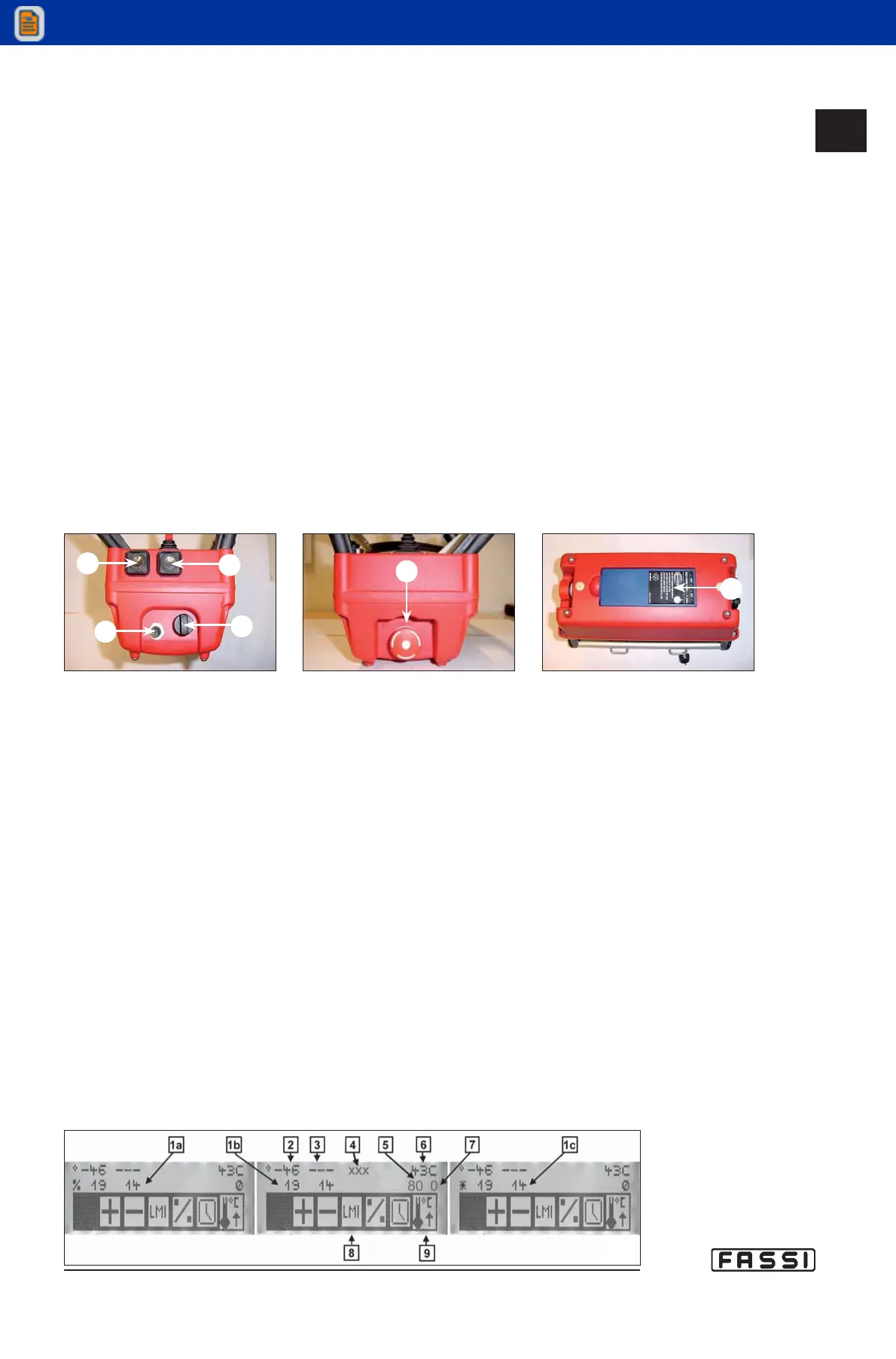
Check the list down below to get the meaning of the elements identified with letters
of the alphabet as they are displayed when turning on the push-button panel, as
shown in figure 8.
1 a. Load on the crane lifting rams, expressed in percentage.
1 b. Pressure in the crane lifting rams, expressed in bars.
1 c. Pressure in the crane lifting rams, expressed in daPsi*.
2. Crane angle monitored by the angle sensor placed on the outer boom.
3. Hydraulic extension angle monitored by the angle sensor placed on
extension arm (the extension is not present in this case).
4. Space for messages.
5. Load on the winch (if fitted), expressed in percentage.
6. Oil temperature monitored by the temperature sensor.
7. Pressure in the hydraulic distributor .
8. Icons.
9. Flags.
The second line of the display can indicate too particular conditions of the crane
through messages like WARNING, ALARM, STOP ROTATION, etc.
In this case, all the data on the second line disappear at the moment and will reap-
pear automatically when the crane control is taken again.
CONTROLS TO
OPERATE THE CRANE
GR4_5-EVOLUTION
fig.8
fig. 5
M
fig. 7
N
fig. 6
G
F
I
L
14.2.2