L) Connection point to the cable that serves to connect the radio remote con-
trol to the electronic unit installed on the crane. The radio remote control is
supplied with a 10 m. length serial cable to connect the radio remote con-
trol to the electronics present on the crane.
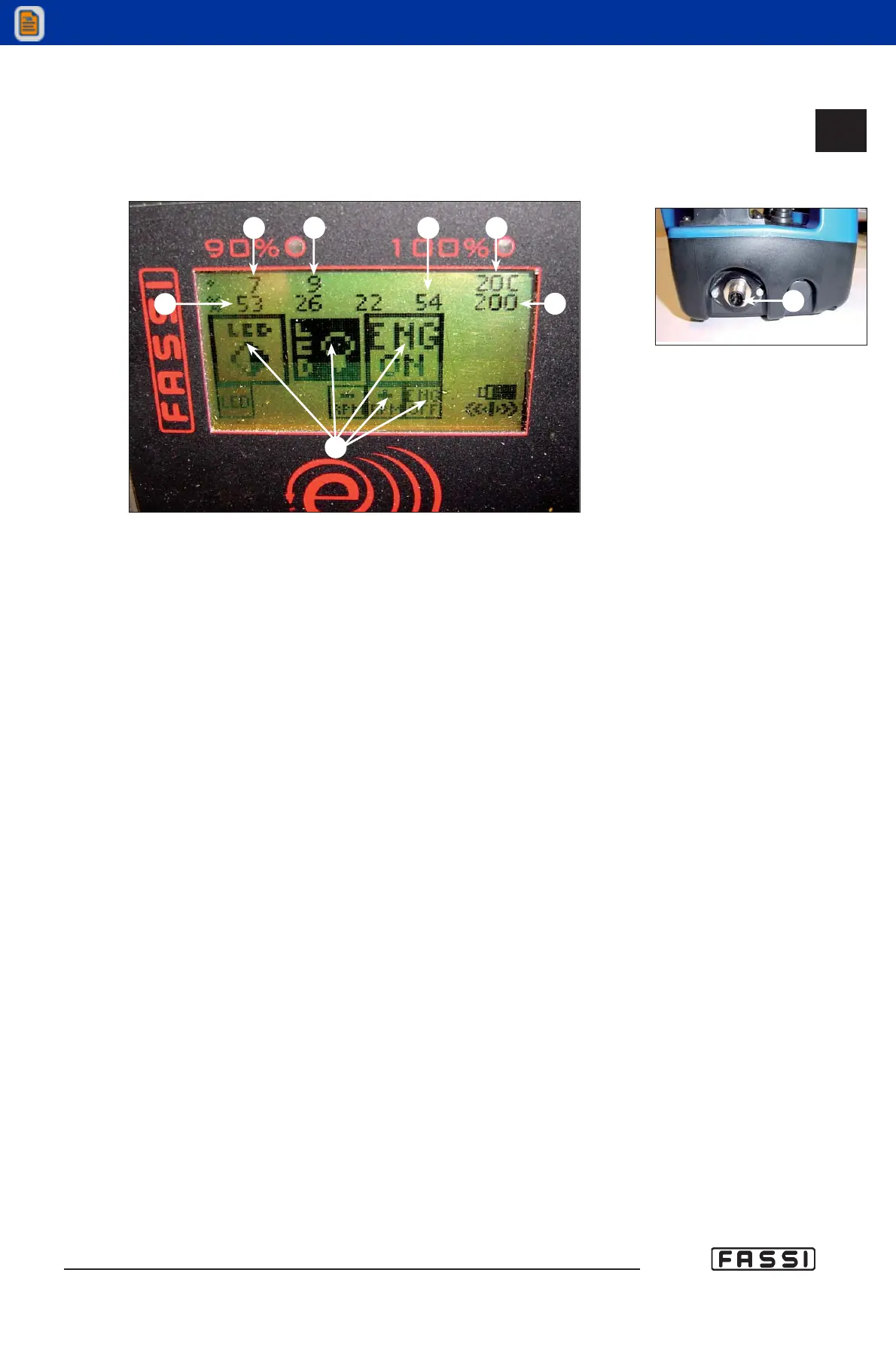
M) Angular position of the crane, read by the angular sensor applied on
the outer boom.
N) Angular position of the hydraulic extension. If the hydraulic extension isn't
present, no value will be visualized. If the hydraulic jib is present but not
attached, it will be visualized “---“.
P) Load percentage on the winch.
Q) The oil temperature, read by the temperature sensor applied on the heat
exchanger.
R) Load indication on: the inner ram, the outer ram, the hydraulic extension (if
fitted).
S) Working pressure in the distributor bank.
T) Virtual Button VB.
- FIRST ACTIVATION OF THE RADIO REMOTE CONTROL AND PROCEDURE
OF AUTOLEARNING
When the radio remote control is installed, and in case it is required to be replaced,
the following procedure is required before it is operated:
1. Insert the battery in the radio remote control.
2. Connect the radio remote control to the crane through the serial cable.
3. Switch on electrically the crane, and after approx. 15 seconds (when the
electronics is activated completely) push and keep pushed the button “ON”
on the radio remote control until the display shows the inscription
“Learnmode OK. Please power off”. Switch off the radio remote control.
Switch off the crane.
4. Remove the serial cable and switch the radio remote control on again.
5. Wait for approx. ten (10) seconds.
6. Electrically feed the crane to put the electronic card under tension (FX800);
the radio remote control display will show “updating Gui version”.
7. Wait approx. three (3) minutes to allow loading of all the icons on the
display. When the display shows “Icons updated please power off”, switch
off and restart the radio remote control panel.
8. The crane can now be operated
fig. 12
L
CONTROLS TO
OPERATE THE CRANE
GR4_5-EVOLUTION
M
N
P
Q
R
S
T
fig. 13
14.2.3