EasyManuals Logo
Home>Fastech>Controller>Ezi-Servo Plus R

Fastech Ezi-Servo Plus R User Manual

Fastech Ezi-Servo Plus R
104 pages
To Next Page IconTo Next Page
To Previous Page IconTo Previous Page
Page #67 background imageLoading...
Page #67 background image
www.fastech.co.kr
67
10. Control I/O Signal
10) Brake Output for high current
This function can be used when the Brake signal is assigned to one of OUTPUT1~
OUTPUT9 of CN1 connector. This is used for protect motor rotation in
Servo ON status. The signal timing diagram between Servo ON command and
Brake signal is same as 9) BRAKE+ and BRAKE- Output.
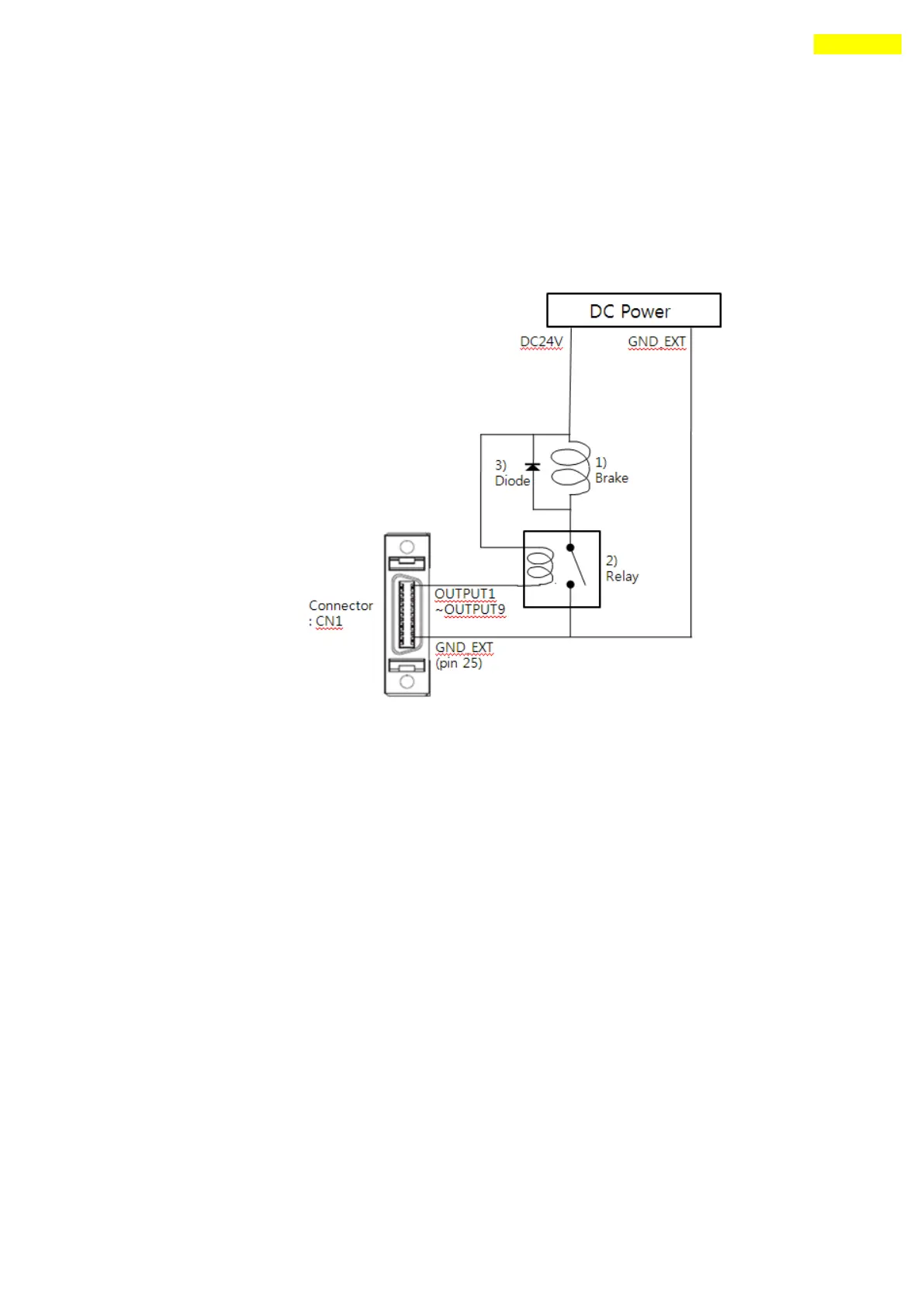
This signal used for the Brake that is over 200[mA]/DC24V of current
consumption. Brake, Relay and diode is needed for this function and the
signal connection diagram is as follows.
*1 Brake : User selected Brake
*2 Relay : under 15[mA] / DC24V
*3 Diode : 1N4004 or equivalent

Table of Contents

Questions and Answers:

Question and Answer IconNeed help?

Do you have a question about the Fastech Ezi-Servo Plus R and is the answer not in the manual?

Fastech Ezi-Servo Plus R Specifications

General IconGeneral
BrandFastech
ModelEzi-Servo Plus R
CategoryController
LanguageEnglish

Related product manuals