Home
Fayat Group
Construction Equipment
Dynapac SD2500C
Page 441 (Seals and sealing rings (5))
Fayat Group Dynapac SD2500C - Seals and sealing rings (5)
588 pages
Manual
Save Page as PDF
To Next Page
To Next Page
To Previous Page
To Previous Page
Loading...
F 40 9
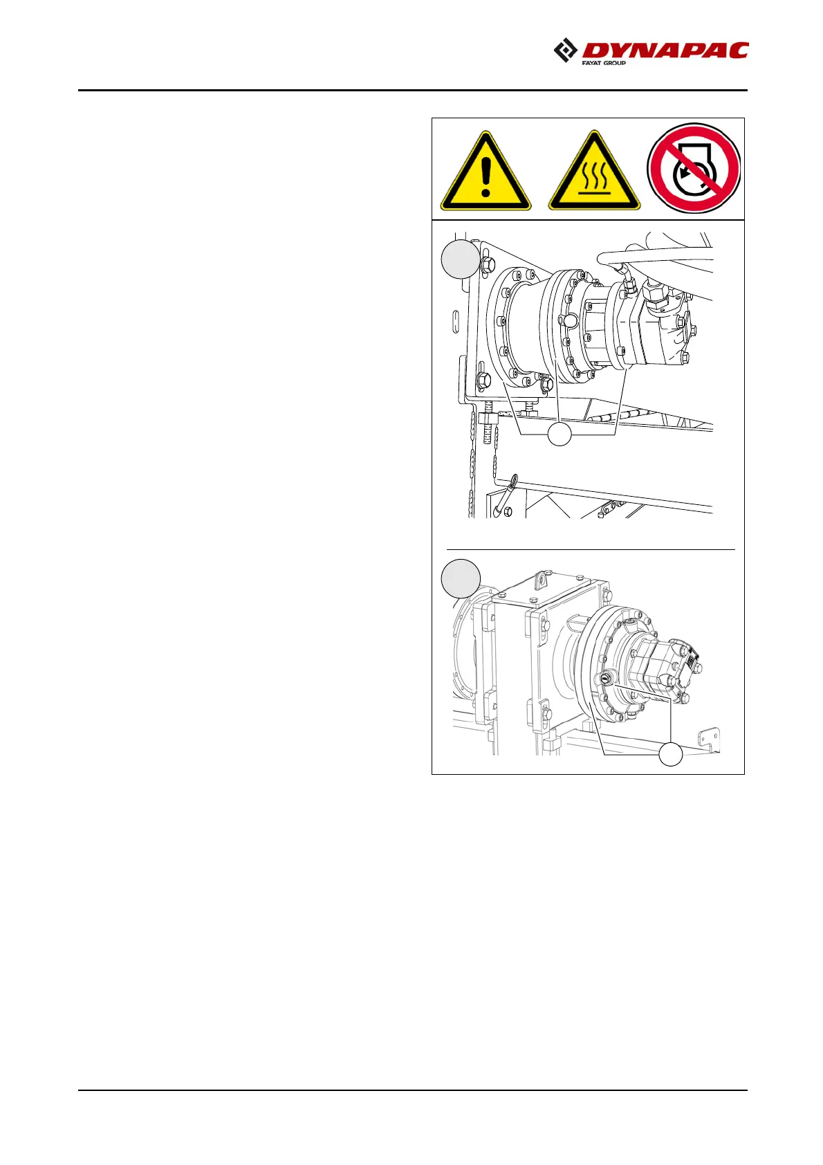
Seals and sealing rings (5)
A
After reaching operating temperature,
check the gearbox for leaks.
m
In case of visible leaks, e.g. between the
flange surfaces (A)
of the gearbox, re-
placement of the s
eals and se
aling rings
is necessary.
I
II
A
A
440
442
Table of Contents
Main Page
Table of contents
3
V Preface
15
1 General safety instructions
16
1.1 Laws, guidelines, accident prevention regulations
16
1.2 Safety signs, signal words
17
"Danger"!
17
"Warning" !
17
"Caution" !
17
"Note" !
17
1.3 Other supplementary information
17
1.4 Warnings
18
1.5 Prohibitive symbols
20
1.6 Protective equipment
21
1.7 Environmental protection
22
1.8 Fire prevention
22
1.9 Additional information
23
2 CE identification and Declaration of Conformity
24
3 Guarantee conditions
24
4 Residual risks
25
5 Sensibly predictable incorrect usage
26
A Correct use and application
27
B Vehicle description
29
1 Application
29
2 Description of assemblies and functions
30
2.1 Vehicle
31
Construction
31
3 Danger zones
36
4 Safety devices
37
5 Technical data, standard configuration
39
5.1 Dimensions (all dimensions in mm)
39
5.2 Allowed angle of rise and slope
40
5.3 Permissible approach angle
40
5.4 Weights SD2500C (all weights in t)
41
5.5 Weights SD2500CS (all weights in t)
41
5.6 Performance data SD2500C
42
5.7 Performance data SD2500CS
43
5.8 Travel drive/traction unit
44
5.9 SD2500C - Engine EU IIIa / Tier 3 (o)
44
5.10 SD2500CS - Engine EU IIIa / Tier 3 (o)
44
5.11 SD2500C - Engine EU IIIb / Tier 4i (o)
45
5.12 SD2500CS - Engine EU IIIb / Tier 4i (o)
45
5.13 SD2500C - Engine Engine EU IV / Tier 4final (o)
46
5.14 SD2500CS - Engine Engine EU IV / Tier 4final (o)
46
5.15 Hydraulic system
47
5.16 Material compartment (hopper)
47
5.17 Material transfer
47
5.18 Material distribution
47
5.19 Screed lifting device
48
5.20 Electrical system
48
5.21 Permissible temperature ranges
48
6 Location of instruction labels and identification plates
49
6.1 Warning signs
52
6.2 Information signs
55
6.3 CE marking
57
6.4 Instructive symbols, prohibitive symbols, warning symbols
58
6.5 Danger symbols
59
6.6 Further warnings and operating instructions
60
6.7 Identification label for the paver finisher (41)
62
6.8 Explanation of 17PIN serial number
63
6.9 Engine type plate
64
7 EN standards
65
7.1 Continuous sound pressure SD2500C
65
7.2 Operating conditions during measurement
65
7.3 Measuring point configuration
65
7.4 Continuous sound pressure SD2500CS
66
7.5 Operating conditions during measurement
66
7.6 Measuring point configuration
66
7.7 Vibration acting on the entire body
67
7.8 Vibrations acting on hands and arms
67
7.9 Electromagnetic compatibility (EMC)
67
C 11 Transportation
69
1 Safety regulations for transportation
69
2 Transportation on low-bed trailers
70
2.1 Preparations
70
3 Securing the load
72
3.1 Prepare the low loader
72
3.2 Driving onto the low-bed trailer
73
3.3 Lashing equipment
74
3.4 Loading
75
3.5 Preparing the vehicle
76
4 Securing the load
77
4.1 Securing at the sides
77
4.2 Securing at the front
77
4.3 Securing at the rear - screed with side board
78
4.4 Securing at the rear - screed without side board
79
Step 1 - fasten lashing straps
79
Step 2 - fasten lashing chains
79
5 Control panel transport safeguard:
80
5.1 After transportation
81
Protective roof (o)
82
6 Transportation
84
6.1 Preparations
84
6.2 Driving mode
86
7 Loading by crane
87
8 Towing
90
9 Safely parking the vehicle
93
9.1 Lifting the vehicle with hydraulic lifts, lifting points
94
D 11 Operation
95
1 Safety regulations
95
2 Controls
97
2.1 Operating panel
97
3 Remote control
154
D 22 Operating the display
173
1 Operation of the input and display terminal
174
Button layout on the display
174
1.1 Menu operation - procedure for adjusting parameters
176
Selecting and changing an adjustment parameter in a menu
178
Selecting and changing a selection possibility in a menu
179
2 Menu structure
180
Menu of the "Home" displays
180
Displays:
180
"HOME" menu - sub-menus
182
"Home" functions / "Quick Settings"
184
"Engine Speed" menu / Engine measured value display
186
"Material Management" measured value display
187
"Screed Heater" adjustment and display menu (o)
188
"Paving Area / Automatic Steering Unit" menu
189
"Front wheel drive" measured value display (o)
190
"Particulate filter regeneration" menu (o)
191
"Paving parameters" menu
193
Adjusting the paving parameters
195
Overview "Course Thickness Parameters"
196
"Camera display" menu (o)
197
"Error Memory" menu
198
Detailed display "Error Messages With Travel Drive Stop"
199
Detailed display "Vehicle Warning Messages"
200
Detailed display "Engine Error Messages"
201
"Basic" menu
202
"Service" menu
203
"Info & Settings" menu
204
Display of the following information:
204
"Screed" set-up menu
205
"Paving / Travel" set-up menu
207
"Truck Assist / Set Assist" set-up menu
209
"Day/Night Lighting" set-up menu
210
"Display" set-up menu
211
"Camera / display" set-up menu
212
"Licence text" display
213
2 Terminal error messages
214
Status, warning and error messages symbols
214
2.1 Drive engine error codes
220
2.2 Error codes
224
3 Menu structure of the setting and display menus
264
D 30 Operation
265
1 Operating elements on the paver finisher
265
1.1 Control elements on the operator's control station
265
Protective roof (o)
266
Ladder
268
Storage space
268
Control platform, moveable (o)
269
Control platform lock (o)
270
Operating panel
271
Protective cabin (o)
272
Windscreen wiper
273
.Emergency actuation control platform, movable
274
Seat console
275
Driver's seat, type I
276
Driver's seat, type II
277
Fuse box
278
Batteries
279
Main battery switch
279
Hopper transport safeguard
280
Screed lock, mechanical (o)
280
Screed lock, hydraulic (o)
281
Paving thickness indicator
282
Auger lighting (o)
283
Engine compartment lighting (o)
283
LED working light (o)
284
500 watt spotlight (o)
285
Camera (o)
285
Auger height adjustment ratchet (o)
286
Auger height indicators
286
Sensor rod / sensor rod extension
287
Manual separator fluid spray (o)
289
Separator fluid spraying system (o)
290
Conveyor limit switches - PLC version
291
Conveyor limit switches - conventional version
292
Ultrasonic auger limit switches (left and right) - PLC version
293
Ultrasonic auger limit switches (left and right) - conventional version
294
24 volt / 12 volt sockets (o)
295
Pressure control valve for screed charging/relieving
296
Pressure control valve for paving stop with relieving
296
Manometer for screed charging/relieving
296
Central lubrication system (o)
297
Lane clearer (o)
298
Screed eccentric adjustment
299
Push roller crossbar, adjustable
300
Push roller crossbar, hydraulically extendable (o)
301
Push roller damping, hydraulic (o)
301
Fire extinguisher (o)
302
First-aid kit (o)
302
Rotary beacon (o)
303
Fuelling pump (o)
304
Illuminated balloon (o)
305
Installation and operation
306
Maintenance
307
Replacing the lamp
307
Truck Assist (o)
308
D 41 Mode of operation
309
1 Preparing for operation
309
Required devices and aids
309
Before starting work (in the morning or when starting paving)
311
Check list for the machine operator
311
1.1 Starting the paver finisher
314
Before starting the paver finisher
314
"Normal" starting
314
External starting (starting aid)
316
After starting
319
Observe indicator lamps
321
Engine coolant temperature check (A)
321
Battery charge indicator lamp (B)
321
Diesel engine oil pressure indicator lamp (C)
321
Travel drive oil pressure indicator lamp (D)
323
1.2 Preparation for transportation
325
Driving and stopping the paver finisher
327
1.3 Preparations for paving
328
Separator fluid
328
Screed heater system
328
Direction marks
329
Loading/conveying material
331
1.4 Starting for paving
333
1.5 Checks during paving
334
Paver function
334
Quality of the layer
334
1.6 Paving with "screed control at paving stop" and "screed charging/relieving"
335
General
335
Screed charging/relieving
337
Screed control with paver finisher stop / in paving operation (screed stop / paving stop / floating paving)
337
Adjusting the pressure
341
Setting pressure for screed control with paving stop + relieving:
341
1.7 Interrupting/terminating operation
343
During breaks in paving (e.g. delay due to material trucks)
343
During longer breaks (e.g. lunch break)
343
When work is finished
345
2 Malfunctions
346
2.1 Problems during paving
346
2.2 Malfunctions on the paver finisher or screed
348
E 10 Set-up and modification
351
1 Special notes on safety
351
2 Distribution auger
352
2.1 Height adjustment
352
Grain sizes up to 16 mm
352
Grain sizes > 16 mm
352
2.2 Mechanical adjustment with ratchet (o)
353
2.3 Hydraulic adjustment (o)
353
2.4 Height adjustment for large working widths / with brace
354
3 Auger extension
356
3.1 Mounting extension parts
357
Mounting the material shaft and auger extension
357
Mounting the outer auger bearing
358
Mounting the auger end bearing
359
3.2 Auger extension chart
360
Auger upgrading, working width 3.14 m
362
Auger upgrading, working width 3.78 m
362
Auger upgrading, working width 4.42 m
362
Auger upgrading, working width 5.06 m
363
Auger upgrading, working width 5.70 m
363
Auger upgrading, working width 6.34 m
364
Auger upgrading, working width 6.98 m
365
Auger upgrading, working width 7.62 m
366
Auger upgrading, working width 8.26 m
367
Auger upgrading, working width 8.90 m
368
3.3 Mounting the auger brace
369
3.4 Aligning the auger
371
3.5 Material shaft, hinged
372
3.6 Hopper scraper
373
3.7 Crossbeam guide
374
4 Offsetting the screed
375
5 Levelling
376
5.1 Slope controller
376
5.2 Mounting the sensor arm
377
5.3 Mounting the grade control system
377
5.4 Setting up the sensor arm
378
5.5 Big ski 9 m, big ski 13 m
379
Mounting the big ski bracket on the crossbeam
381
Mounting the swivel arms
382
Mounting the centre element
383
Extending the big ski
384
Mounting the sensor bracket
385
Mounting and aligning the sensors
386
Mounting the distributor box
387
Connection diagram
388
5.6 Levelling shoe 6m, 9m
389
6 Automatic steering unit
391
6.1 Mounting the automatic steering unit on the paver finisher
392
Mounting and aligning the sensor
393
Connecting the sensor
393
Automatic steering unit operating instructions
394
7 Emergency stop during feeder operation
395
8 Limit switch
396
8.1 Auger limit switches (left and right) - mounting the PLC version
396
8.2 Auger limit switches (left and right) - mounting the conventional version
397
9 Special accessories
398
9.1 Material bucket
398
Application
398
Description of assemblies and functions
399
Technical data
400
Dimensions, bucket MH2500 - (short version)
400
Dimensions, bucket MH2550 - (long version)
401
Weights
402
Volume
402
10 Identification points
403
10.1 Information signs
404
10.2 Warning signs
404
10.3 Further warnings and operating instructions
404
10.4 Instructive symbols, prohibitive symbols, warning symbols
405
Load securing - bucket
406
Prepare the low loader
406
Lashing equipment
407
Lashing
408
Loading with the crane - MH2500
410
Loading with the crane - MH2550
411
Lash the bucket in the paver
413
Operation
415
Operation with a feeder with slewing belt
416
Preparations for paving
416
Separator fluid
416
Cleaning the bucket
417
11 Screed
418
12 Electrical connections
418
12.1 Machine operation without remote control / side board
419
F 10 Maintenance
421
1 Notes regarding safety
421
F 25 Maintenance review
423
1 Maintenance review
423
F 31 Maintenance - conveyor
425
1 Maintenance - conveyor
425
1.1 Maintenance intervals
427
1.2 Points of maintenance
428
Chain tension, conveyor (1)
428
Conveyor drive - drive chains (2)
430
Conveyor deflectors / conveyor plates (3)
431
F 40 Maintenance - auger assembly
433
1 Maintenance - auger assembly
433
1.1 Maintenance intervals
435
1.2 Points of maintenance
437
Outer auger bearing (1)
437
Auger planetary gear (2)
438
Drive chains of the augers (3)
439
Auger box (4)
440
Seals and sealing rings (5)
441
Gearbox bolts Check tightening (6)
442
Mounting screws - Outer auger bearing Check tightening (7)
443
Auger blade (8)
444
F 50 Maintenance - engine assembly Tier 3 (o)
445
1 Maintenance - engine assembly
445
1.1 Maintenance intervals
447
1.2 Points of maintenance
450
Engine fuel tank (1)
450
Engine lube oil system (2)
451
Engine fuel system (3)
454
Engine air filter (4)
456
Engine cooling system (5)
458
Engine drive belt (6)
460
F 52 Maintenance - engine assembly Tier 4i (o)
461
1 Maintenance - engine assembly
461
1.1 Maintenance intervals
463
1.2 Points of maintenance
466
Engine fuel tank (1)
466
Engine lube oil system (2)
467
Engine fuel system (3)
470
Engine air filter (4)
472
Engine cooling system (5)
474
Engine drive belt (6)
476
Crankshaft ventilation filter (7)
477
Exhaust system - particulate filter (8)
478
F 54 Maintenance - engine assembly Tier 4F (o)
479
1 Maintenance - engine assembly
479
1.1 Maintenance intervals
481
1.2 Points of maintenance
485
Engine fuel tank (1)
485
Engine lube oil system (2)
487
Engine fuel system (3)
490
Change extraction filter (o)
492
Engine air filter (4)
493
Engine cooling system (5)
495
AdBlue® / DEF tank (6)
497
AdBlue® / DEF tank - suction filter
500
Filter change < / = s/n 003055
502
Filter change > / = s/n 003056
505
AdBlue® / DEF tank - tank cover
508
AdBlue® / DEF dosing unit
510
Engine drive belt (7)
511
Crankshaft ventilation filter (8)
512
Exhaust system - diesel oxidation catalytic converter (9)
513
F 60 Maintenance - hydraulic system
515
1 Maintenance - hydraulic system
515
1.1 Maintenance intervals
517
1.2 Points of maintenance
519
Hydraulic oil tank (1)
519
Suction/return flow hydraulic filter (2)
521
Bleeding the filter
522
Ventilation filter
522
High-pressure filter (3)
523
Pump distribution gear (4)
524
Bleeder
525
Hydraulic hoses (5)
526
Marking hydraulic hoses / storage period, period of use
528
Auxiliary flow filter (6)
529
F 73 Maintenance – drive units
531
1 Maintenance – drive units
531
1.1 Maintenance intervals
533
1.2 Points of maintenance
536
Chain tension (1)
536
Bottom plates (2)
539
Rollers (3)
540
Planetary gear (4)
541
Screw connections
543
F 81 Maintenance - electrical system
545
1 Maintenance - electrical system
545
1.1 Maintenance intervals
547
1.2 Points of maintenance
548
Batteries (1)
548
Recharging the batteries
549
Alternator (2)
550
Insulation faults
551
Cleaning the generator
552
Electrical fuses / relays (3)
553
Fuses in terminal box (B)
554
Relays in terminal box (C)
556
Relays in the engine compartment (E)
558
F 90 Maintenance - lubricating points
559
1 Maintenance - lubricating points
559
1.1 Maintenance intervals
560
1.2 Points of maintenance
561
Central lubrication system (1)
561
Bearing points (2)
565
F 100 Tests, stopping ...
567
1 Tests, checks, cleaning, stopping
567
1.1 Maintenance intervals
568
2 General visual inspection
569
3 Check that the bolts and nuts fit firmly
569
4 Inspection by an expert
570
5 Cleaning
571
5.1 Cleaning the hopper
572
5.2 Cleaning the conveyor and auger
572
5.3 Cleaning optical or acoustic sensors
573
6 Preserving the paver finisher
574
6.1 Shutdowns for up to 6 months
574
6.2 Shutdowns lasting from 6 months to 1 year
574
6.3 Recommissioning the machine
574
6.4 Operating the vehicle in special climatic conditions or environments.
575
7 Environmental protection, disposal
576
7.1 Environmental protection
576
7.2 Disposal
576
8 Bolts - torques
577
8.1 Standard metric threads - strength class 8.8 / 10.9 / 12.9
577
8.2 Fine metric threads - strength class 8.8 / 10.9 / 12.9
578
F 114 Lubricants and operating substances
579
1 Lubricants and operating substances
579
1.1 Capacities
581
2 Operating substance specifications
582
2.1 Drive engine TIER 4i, 4F / Stage IIIb, IV (o)- fuel specification
582
2.2 Drive engine - Lube oil
582
2.3 Cooling system
582
2.4 Hydraulic system
583
2.5 Pump distribution gear
583
2.6 Drive unit planetary gear
583
2.7 Auger drive planetary gear
583
2.8 Auger box
584
2.9 Grease
584
2.10 Drive engine - AdBlue® / DEF
585
2.11 Hydraulic oil
586
Related product manuals
Fayat Group Dynapac CA25
107 pages
Fayat Group Dynapac CC800
122 pages
Fayat Group Dynapac CC900G
122 pages
Fayat Group DYNAPAC CA5000
170 pages
Fayat Group DYNAPAC CA6000
178 pages
Fayat Group DYNAPAC CA4600
178 pages
Fayat Group DYNAPAC CC224HF
174 pages
Fayat Group BOMAG BW 213 D-5
290 pages
Fayat Group BOMAG BW 226 DH-4
51 pages
BOMAG BW 213 DH-4 BVC
51 pages
Fayat Group BOMAG BW177PDH-50
114 pages
Fayat Group BOMAG BF 700 C S600
31 pages