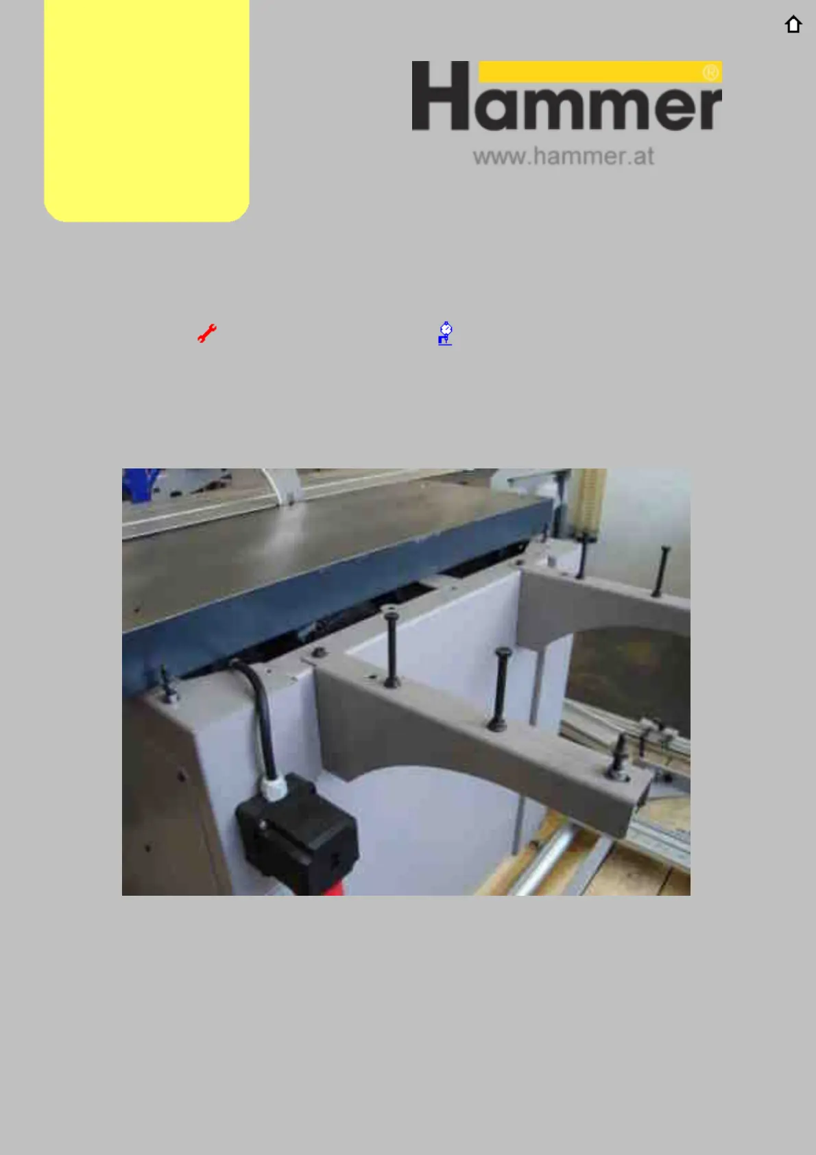
Extension tables
Using the exploded assembly diagrams supplied with the machine, determine the
correct screws to use for the extension table(s). Begin as shown in the picture below
wi
th the support members. Note: Machines with 48" (1250mm) rip capacity also
have an additional support member not shown in the pictures below, but in later steps.
(picture shows full length 31" (800mm) Rip capacity)
Adju s t m e n t Lin k Alig nm e nt Lin k
Continued…
11.Assembly