DIVA D C24
42 EN
cod. 3542B920 - Rev 00 - 11/2022
• The card goes to the setting “q01”; displaying the currently saved value by pressing the DHW buttons.
• If the minimum pressure read on the pressure gauge is different from the nominal one, proceed in increments/de-
crements of 1 or 2 units of the parameter “q01” by pressing the DHW buttons: after each change, the value is stored;
wait 10 seconds for the pressure to stabilise.
• Recheck both settings by pressing the heating buttons and if necessary correct them by repeating the procedure
described above.
• Pressing the Eco/Comfort button for 2 seconds returns to TEST mode.
• Deactivate TEST mode (see next par.).
• Disconnect the pressure gauge.
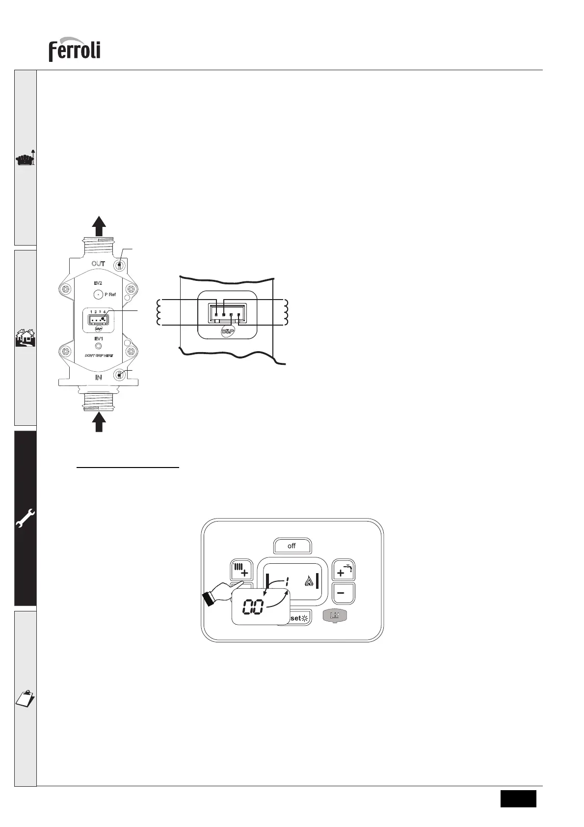
TEST mode activation
Press the heating buttons (details 3 and 4 - fig. 1) for 5 seconds to activate TEST mode. The boiler lights at the maxi-
mum heating power set as described in the next paragraph.
The heating and DHW symbols (fig. 13) flash on the display; the heating power will appear alongside.
fig. 13- TEST mode (heating power = 100%)
Press the heating buttons (details 3 and 4 - fig. 1) to increase or decrease the power (Minimum=0%, Maximum=100%).
By pressing the DHW “-” button (detail 1 - fig. 1), boiler output is immediately adjusted to minimum (0%). By pressing
the DHW “+” button (detail 2 - fig. 1), boiler output is immediately adjusted to maximum (100%).
If the TEST mode is activated and enough hot water is drawn to activate the DHW mode, the boiler remains in TEST
mode but the 3-way valve goes to DHW.
To deactivate the TEST mode, press the heating buttons (details 3 and 4 - fig. 1) at the same time for 5 seconds.
The TEST mode is automatically disabled in any case after 15 minutes or by not drawing hot water (if enough hot water
has been drawn to activate the DHW mode).
fig. 11 - Gas valve
A - Upstream pressure point
B - Downstream pressure point
I - Gas valve electrical connection
R - Gas outlet
S - Gas inlet
fig. 12 - Gas valve connection
TYPE SGV100
Pi max 65 mbar
24 Vdc - class B+A
I
I
I
I
I
I
I
I
I
I
I
I
I
I
I
I
I
I
I
I
I
I
I
I
I
I
I
I
I
I
I
I
I
I
I
I
I
I
I
I
I
 Loading...