103
EN
Cod. 3541T090 - Rev. 00 - 06/2019
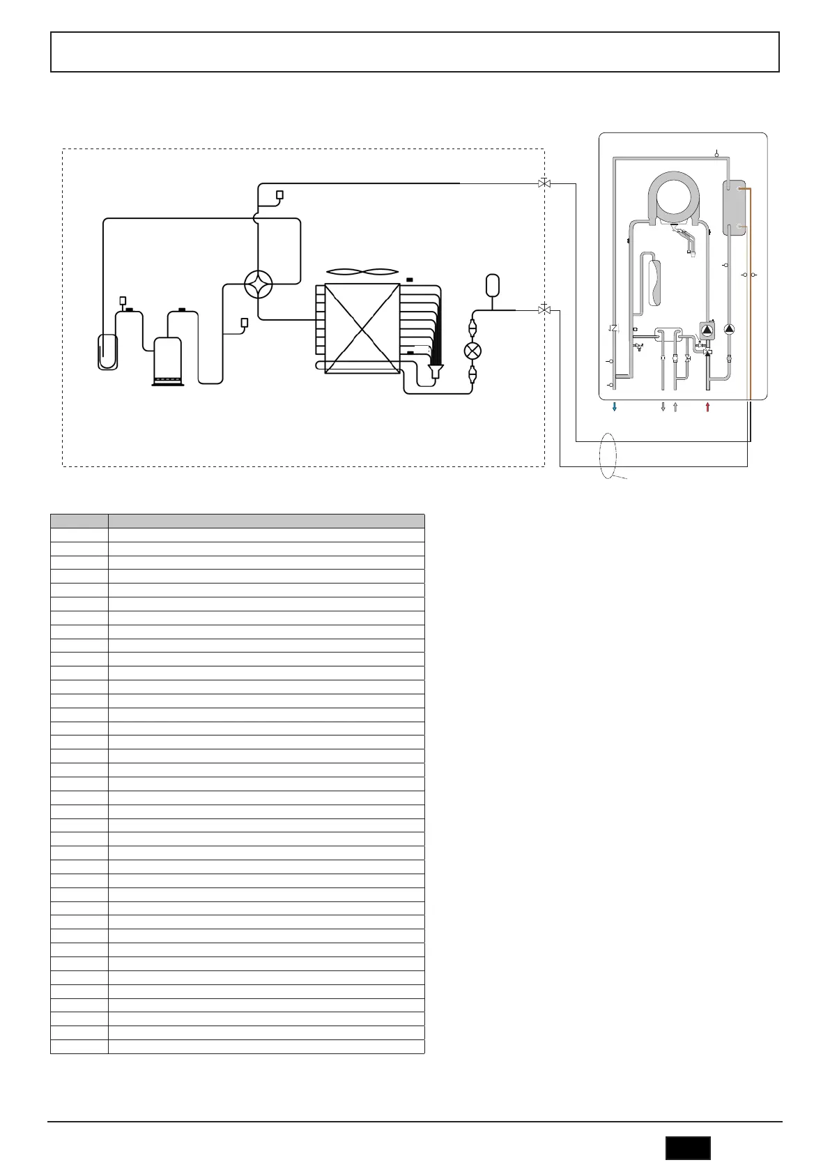
REFRIGERANT DIAGRAM
17. REFRIGERANT DIAGRAM
265
264
Th
Tp
250
266
255
Pe
T4
260
262
261
258
259
258
257
T3
256
241
194
14
G
L
114
95
74
56
193
186
34
10
11
8
9
42
36
32
TW_in
TW_out
CHP
SPHP
FL
136
T1
T1b
17
T2BT2
Outdoor unit
Indoor unit
Refrigerant connections
fig. 199 -
- Description
8
Sanitary water outlet
9
Domestic water inlet
10
Plant delivery
11
System return
14
Safety valve
27
Electric booster (available as an option)
32
Circulator
36
Automatic air vent
56
Expansion vessel
95
3-way diverter valve
250
Compressor
255
Cycle inversion valve
256
Coil
257
Distributor
258
Filter
259
Electronic expansion valve
260
Liquid receiver
261
Liquid tap
262
Gas tap
264 Liquid separator
265 Low pressure switch
266 High pressure switch
267 Solenoid valve
268 Capillary
G Gas line
L Liquid line
PDW Water differential pressure switch
Pe Pressure sensor
T1 System delivery water temperature probe (installed as standard on the unit)
T1B Indoor unit outlet water temperature probe
T2 Liquid coolant temperature probe
T2B Gas coolant temperature probe
T3 Liquid / battery temperature probe
T4 Outdoor air temperature probe
Th Compressor suction temperature probe
Tp Compressor flow temperature probe
TW_in Plate heat exchanger inlet water temperature probe
TW_out Plate exchanger outlet water temperature probe
 Loading...