30
EN
Cod. 3541T090 - Rev. 00 - 06/2019
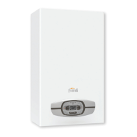
INSTALLATION
Outdoor Unit
Power Supply
3-shield wire
COMANDO
REMOTO
ABXYE
ABXYE
P QET5 T5 T1bT1b
IBH1
J5
J6
J3
IBH2 PE TH NCHA1A2NNNPE
IBH1 IBH2
LPE
PE
N
TH PE TBH L1
AHS1 AHS2
P_oPEPE P_d SV2
Power Supply
LN
EQP
OUTDOOR UNIT
REMOTE
CONTROL
Supply
electricity already
wired at the factory
Power supplie
comunication
(shielded cable)
DETAIL 3A “FIG. 36 -”
fig. 37 -
☞
NOTE
Connect the communication cable between indoor unit and outdoor unit keeping the correspondence of the letters indicated on the terminals (P with P, Q with Q, E with E).
Connect the communication cable between indoor unit and remote control keeping the correspondence of the letters indicated on the terminals (A with A, B with
B....).
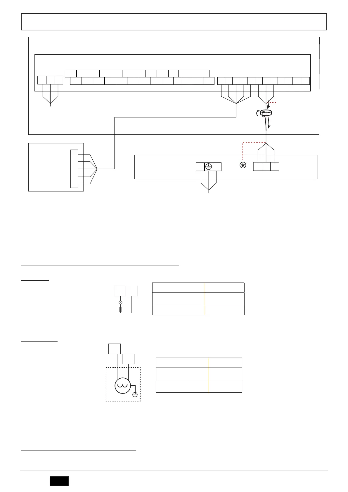
Connections between indoor unit terminal block and plant components
Remote alarm
Voltage
Passive signal port
(dry contact)
Maximum running current
0.5A
Wiring size 0.75mm
2
A1 A2
L
FUSE
N
fig. 38 -
2-way valve (SV2)
Voltage 220-240VAC
Maximum running
current
0.2A
Wiring size 0.75mm
2
SV2
N
fig. 39 -
☞
NOTE
The SV2 valve is powered when the heat pump is operating in HEAT mode.
Room thermostat (ON/OFF - HEAT/COOL by digital input)
External ON / OFF (thermostat)
 Loading...