31
EN
Cod. 3541T090 - Rev. 00 - 06/2019
INSTALLATION
POWER IN
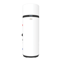
Method B
H
RT
L1
C
fig. 40 -
External COOL/HEAT (thermostat)
Voltage 220-240VAC
Maximum running current
0.2A
Wiring size 0.75mm
2
HEAT
COOL
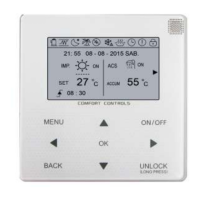
POWER IN
Method A
H
RT
L1
C
fig. 41 -
Method ON/OFF Heat / COOL Digital input effect Remote controller Setup*
A
√
The operation mode is defined by the digital input.
The unit will be ON in COOL mode when L1-C is closed.
The unit will be ON in HEAT mode when H-L1 is closed.
If both digital input are closed the unit will be ON in COOL mode.
The user can only set the
target water flow temp.
ROOM THERMOSTAT
MODE SETTING
DUAL ROOM
THERMOSTAT
YES
NON
YES
NON
YES
NON
6 ROOM THERMOSTAT
ROOM THERMOSTAT
MODE SETTING
DUAL ROOM
THERMOSTAT
SCROLL
YES
NON
YES
NON
YES
NON
B √
The unit will be ON when the digital input is closed.
The unit will operate in the mode defined by the controller.
The user can set the ope-
ration mode and the target
water flow temp.
6 ROOM THERMOSTAT
ROOM THERMOSTAT
MODE SETTING
DUAL ROOM
THERMOSTAT
SCROLL
YES
NON
YES
NON
YES
NON
6 ROOM THERMOSTAT
ROOM THERMOSTAT
MODE SETTING
DUAL ROOM
THERMOSTAT
SCROLL
YES
NON
YES
NON
YES
NON
☞
NOTE: For more details refer to paragraph “ ROOM THERMOSTAT (for more details refer to paragraph “8.8 Room thermostat (ON/OFF - HEAT/COOL by
digital input)”).
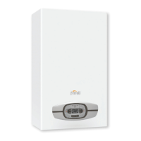
Boiler (AHS)
Connection already made at the factory.
TERMINAL BOILER
(terminals 5 and 6 see “g. 206 -”)
AHS1 AHS2
fig. 42 -
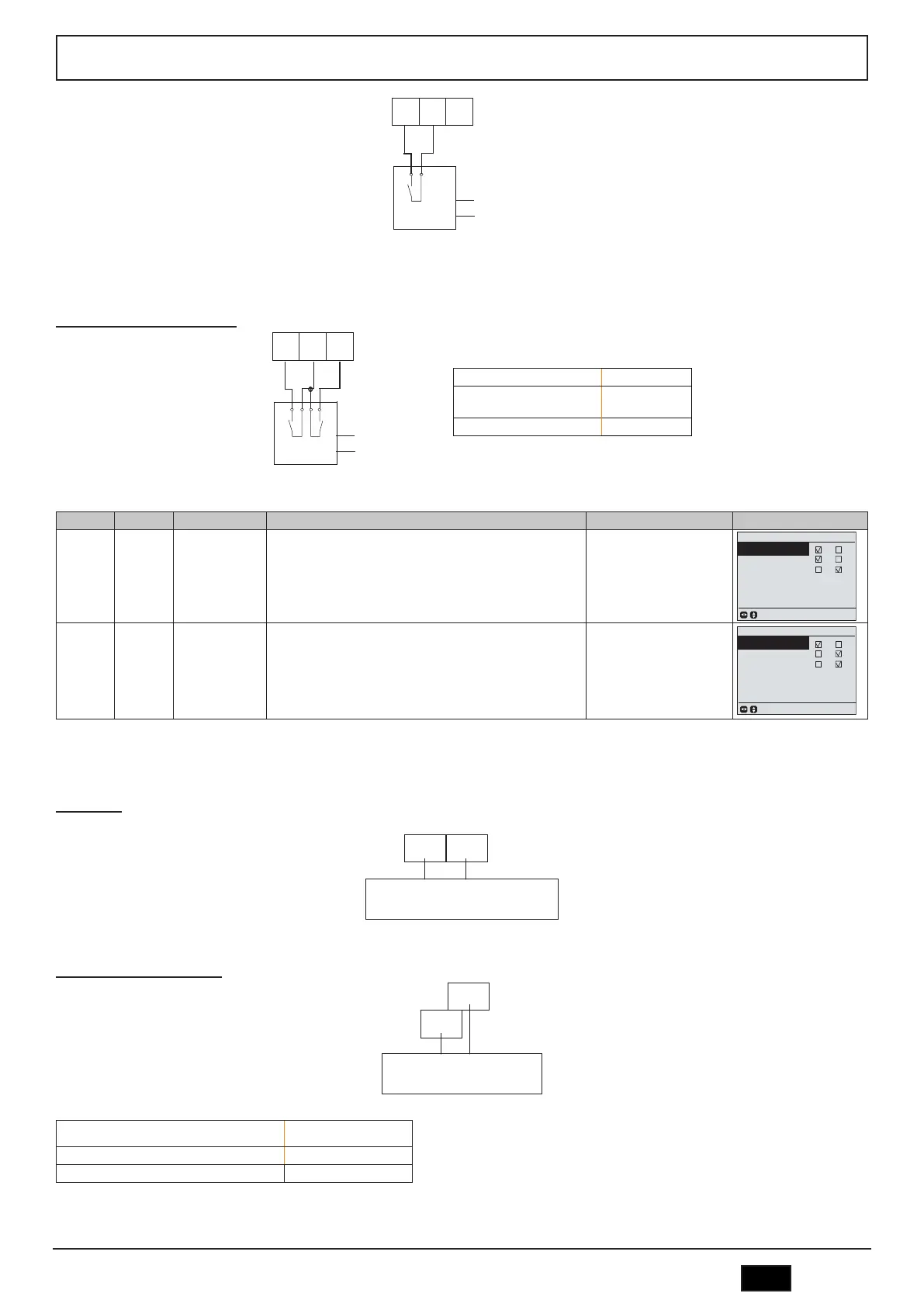
Outside circulation pump (P_o)
P_o outside pump
P_o
N
fig. 43 -
Voltage 220-240VAC
Maximum running current 0.2A
Spessore cablaggio 0.75mm
2
 Loading...