14
EN
Cod. 3541T090 - Rev. 00 - 06/2019
SYSTEM EXEMPLARY SCHEMES
5. SYSTEM EXEMPLARY SCHEMES
FCU1
FHLn
Mn
.......
.......
FCUn
M
18
Mn
Mn
20a
M
20b
TWR
M1
T1_c
T1_h
Tn_c
10
G
L
9
11
8
17
M1
T2_h
Tn_h
FHL1
4
UE
UI
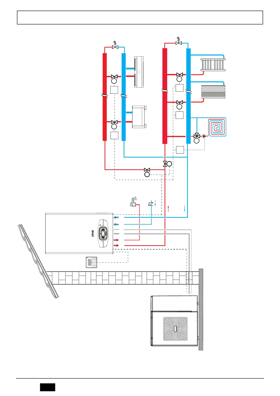
> KEY IU Internal unit EU External unit 4 Wired remote control (provided as standard with the heat pump) 8 DHW outlet - Ø 1/2” 9 DHW inlet - Ø 1/2” 10 System delivery - Ø 3/4” 11 System return - Ø 3/4” 17 Check valve (not supplied) 18 Bypass valve (not sup-
plied) 20a Two-way valve (not supplied), controlled by SV2 20b Two-way valve (not supplied), controlled by SV2 in denied logic G Gas Line l Liquid Line T1_c - Tn_c Cold request room thermostat (not supplied) T1_h - Tn_h Hot request room thermostat (not supplied)
FCU 1...n Air terminal: it can only be used for cooling with radiant floor heating or for cooling and heating without radiant floor FHL 1...n Radiant floor / radiator only heating in zones TWR Integration of towel warmer in bathroom: if connected to the heating system it must
be integrated with an electrical resistor (R) actuated by the control (C) which closes the valve at the same time (M); if not connected to the system, heating is provided by the resistor only (R) actuated by the control (C) - - - - Electrical connections

 Loading...