29
EN
Cod. 3541T090 - Rev. 00 - 06/2019
INSTALLATION
Procedure
1. Remove the front panel ( sez. “15.7 Extraordinary maintenance and replacement of heat pump components” on page 91)
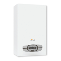
2. Connect the cables to the appropriate terminals as shown on the diagram, taking care to pass the cables through the cable glands on the bottom of the boiler (see
“fig. 35 -” on page 29)
3. Then secure the cables with cable ties.
fig. 35 -
Dati elettrici
Outdoor unit MOD.
04 06 08
Power input "
220-240V 50 Hz
Automatic circuit breaker A 16 20
Power supply cross-section of cable mm
2
3x2,5 3x4,0
Indoor unit MOD.
08
Power input " 220-240V 50 Hz
Automatic circuit breaker A 2
Recommended cable H05RN-F or as installed. See specific legislation. The customer must install the automatic circuit breaker.
Communication cable between indoor and
outdoor unit
MOD.
04 06 08
Wiring size (shielded cable) mm
2
3x0,75
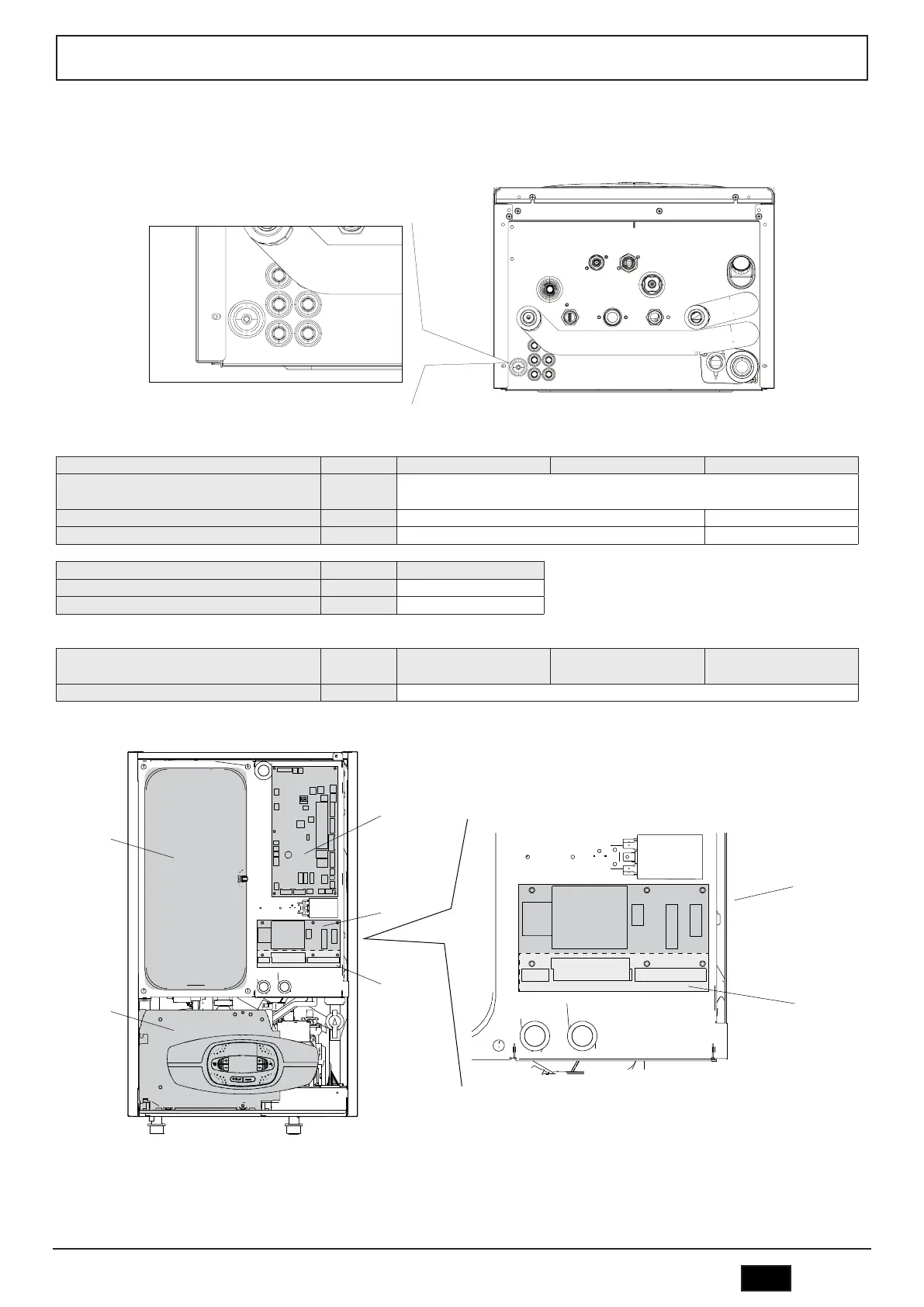
View of the indoor unit without front panel and without panel heat pump electric box
4
56
2
3
3a
J5
J6
J3
J5
J6
J3
3
3a
fig. 36 -
Legend
2 Electronic heat pump board
3 Wiring board
3a Terminal Blocks J5, J6, J3
4 Boiler electric box
56 Expansion vessel
 Loading...