27
EN
Cod. 3541T090 - Rev. 00 - 06/2019
INSTALLATION
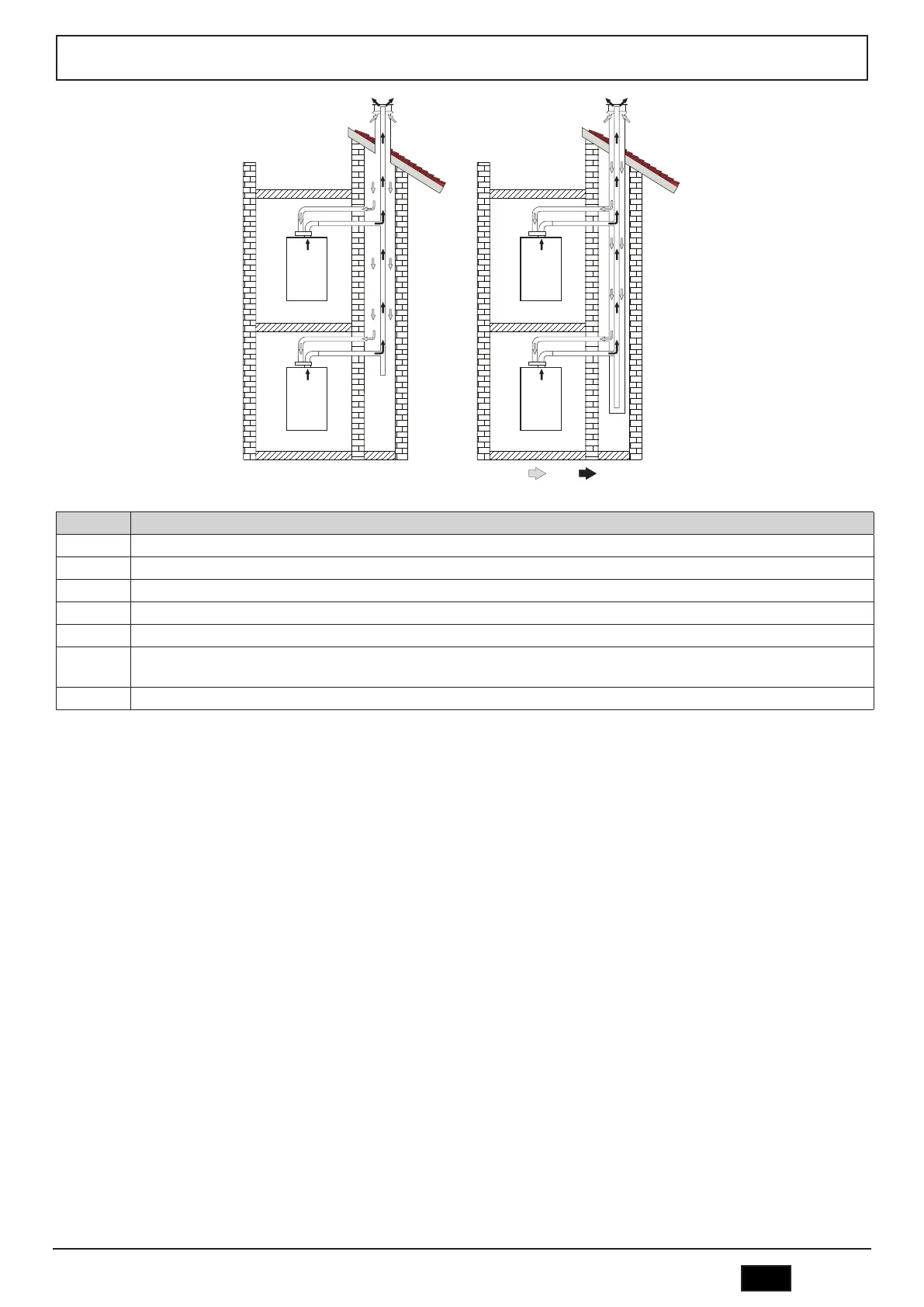
fig. 33 - Connection examples - system C10 and C11 ( = Air / = Fumes)
Table. 6 - Typology
Type Description
C10 Unit connected through its ducts to a system of common flue pipes under pressure obtained in the structure
C11 Unit connected through its ducts to a system of common flue pipes under pressure
C2X Intake and exhaust in common flue (intake and exhaust in same flue)
C4X Intake and exhaust in common and separate flues, but undergoing similar wind conditions
C8X Exhaust in single or common flue and wall intake
B3X
Intake from installation room by means of concentric duct (that encloses the exhaust) and exhaust in common flue with natural draft.
B IMPORTANT- THE ROOM MUST BE PROVIDED WITH APPROPRIATE VENTILATION
C93 Exhaust to a vertical terminal and intake from existing flue.
To connect the boiler to a collective flue or to a single chimney with natural draught, flue or chimney, they must be specifically designed by qualified technical personnel
in compliance with current regulations and be suitable for sealed chamber units equipped with fan.
ONLY FOR THE ITALIAN MARKET
According to Art. 5 Para. 2,. f) and g) of Min. Decree 37/08, gas systems, chimneys, flues and smoke systems with a capacity of over 50 kW and in any case all multiple
flues installed in Italy must be designed by a Professional registered in the appropriate professional registers
Backflow valve
The boiler is equipped as standard with a backflow valve (anti-reflux system), therefore it can be connected to collective positive pressure flues only if running on G20
gas.
With type C10 boiler installation, apply the relevant yellow sticker (included in the bag of documents supplied with the unit) in a CLEARLY VISIBLE PLACE ON THE
FRONT CASING.
After installation, check the tightness of the flueways and gas circuit.
OTHERWISE THERE IS DANGER OF SUFFOCATION DUE TO PRODUCTS OF COMBUSTION ESCAPING.
 Loading...