45
ELECTRICAL CONNECTIONS
KEY TO WIRING DIAGRAMS
MT = Ground terminsl
MO = Main terminal board
CN1 = Motor connector
CN = Control connector
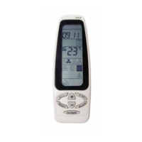
REM = Remote control for function changes (with 230V voltage rating)
EC = Economy function key
MA = Brown wire
GR = Grey wire
G/V = Yellow/green wire
MRS = Red wire (3rd speed-min.)
MBL = Blue wire (2nd speed-med.)
MNE = Black wire (1st speed-max.)
MBI = White wire (common connection)
VE = Green wire
GI = Yellow wire
TC = Enabling thermostat (opt.)
ST = Seasonal selector
SV = Fan speed selector
MV = Fan motor
CV = Fan condenser
SB = Bank probe
SA = Ambient probe
L-EC = Economy Led
L-ON/OFF= ON/OFF Led
IG = Switch at user’s charge with breaking capacity of not less than 4.5 kA
CO = Terminal battery
K1 = Valve/heating element accessory command
TS = Set point variator
VM = ON/OFF valve accessory command (opt.)
ON/OFF = ON/OFF selector
- The dotted lines represent connections at the installer’s charge; wire type H05 VV-K 1.5 mm
2
or depending on
installation. Consult the specific standards.
NOTE: Eliminate the jumper between terminals 4-5 in order to install the TC
 Loading...