For the initial start-up of the motor c ontroller without safety equipment, the motor
controller CMMP-AS-…-M0 with a minimum circuitry corresponding to Fig. 3 can be
wired with an emergency stop switch ( 2 ).
Note
Never bypass safety functions.
Carry out the minimum circuits of the inputs STO-A/S TO-B and 0V-A/0V-B for the
initial start-up so that they will be forcibly removed when the final protection cir-
cuitry is executed.
7 Commissioning
Note
Commissioning does not mean the first intended use by the final customer.
Rather, it means commissioning by the machine manufacturer when the machine
is set up.
Note
Loss of the safety function!
Lack of the safety function can result in serious, irreversible injuries, e.g. due to
uncontrolled movements of the c onnected actuators.
• Operate safety function only when all safety measures have been introduced.
• The safety function must be checked and, prior to the intended use, a corre-
sponding validation must be carried out.
Incorrect wiring or use of incorrect external components which were not selected
corresponding to the safety category can lead to loss of the safety function.
• Carry out a risk a ssessment for your application and select the circuitry and
components accordingly.
7.1 Prior to commissioning
Carry out the following steps in preparation for the initial start-up:
1. Make sure the motor controller is correctly mounted.
2. Check the electrical installation (connecting cable, pin allocation section 6).
Are all PE protective earth conductors connecte d?
7.2 Perfor mance test
Note
The STO function must be validated after the installation and after any modifica-
tion to the installation.
This validation must be documented by the person performing commissioning.
To help you with commissioning, you can find sample checklists in the docu-
mentation GDCP-CMMP-AS-M0-S1-... on the CD accompanying the motor con-
troller .
8Operation
8.1 Obligations of the operator
The operational capability of the safety device is to be checked at adequate inter-
vals. It is the responsibility of the operator to choose the type of check and time
intervals in the specified time period. The check is to be conducted so the flawless
functioning of the safety device in interaction with all the components can be veri-
fied.
8.2 Maintenance and care
The safety function in the motor controller CMMP-AS -...-M0 requires no mainten-
ance.
9 Diagnostics and troubleshooting
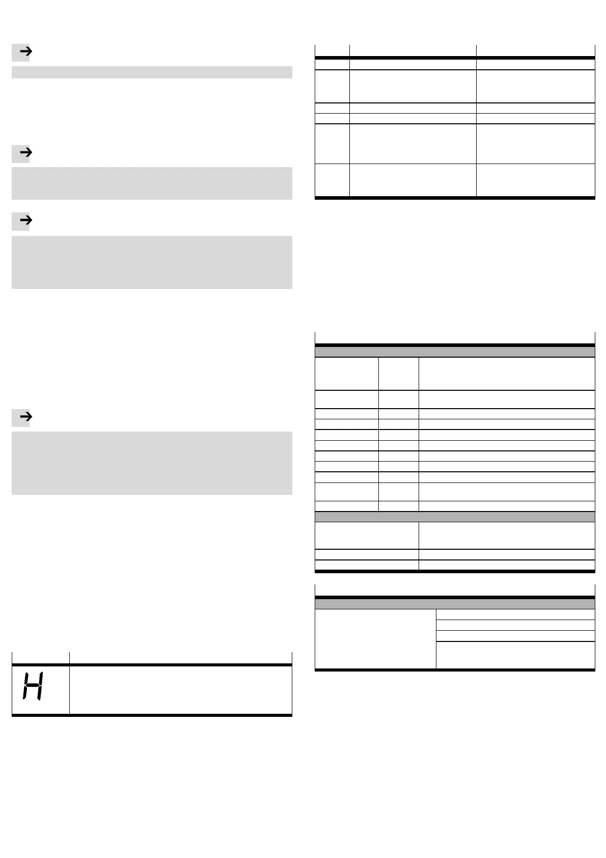
9.1 Status indicators
Display
Description
“H”: The motor controller is in the “safe status”.
This does not mean th e same as the information abo ut the status of the
safety function STO (Safe Torque Off).
For th e “unsafe status”, no special display is intended; the standard status
displays of the motor controller are depicted.
Fig. 4 Seven-segment display on the motor controller
9.2 Error messages
The motor controller displays malfunctions cyclically in the seven-segment display
on the front side of the motor controller. Error messages with “E” (for error), a
main index (xx) and a sub-index (y) display, e.g. E 5 1 0. Warnings have the same
number, but are represented with previous and subsequent middle benches, e.g. -
170-.Fig.5liststheerrormessagesthatarerelevantforfunctionalsafety.
The complete list of error messages can be found in the hardware documenta-
tion G DCP-CMMP-M0-HW-... of the motor controller.
Where error messages cannot be acknowledged, you must first eliminate the
cause. Then reset the motor controller, and chec k whether the cause of the error,
and the error message, have been eliminated.
Error
Cause Actions
51-0
1)
Reserved –
51-1
1)
Safety function: driver function defective
– Internal voltage error of the STO circuit
• Safety circuit defective. No actions
possible; please contact Festo. If
possible, replace with another motor
controller.
51-2
1)
Reserved –
51-3
1)
Reserved –
52-1 Safety function: Discrepancy time has
elapsed
• Control ports STO-A and STO-B are
not actuated simultaneously.
• Control ports STO-A and STO-B are
not wired in th e same way.
• Check discrepancy time.
52-2 Safety function: Failure of driver supply
with active PWM activation
• The safe status was requested with
approved power output stage. Check
inclusio n in the safety-oriented inter-
face.
1)
The messages of error group 51 cannot be acknowledged.
Fig. 5 Error numbers in relationship to the safety functions
10 Repair or replacement of the integrated s afety circuit
A repair or replacement of the integrated safety circuit is not permissible. If re-
quired, exchange the complete motor controller.
11 De-commissioning and waste management
Observe the local regulations for environmentally appropriate disposal of electron-
ic modules.
12 Technical data
Safety engineering
Safety data
Safety function STO – Safe start inhibitor (STO, Safe Torque Off) in accordance
with EN 61800-5-2 with SIL 3
– Safe start inhibitor (STO, Safe Torque Off) in accordance
with EN ISO 13849-1 with category 4 and PL e
SIL SIL 3 /
SILCL3
Safety level (Safety integrity level) in accordance with
EN 61800-5-2 / EN 62061 / IEC 61508
Category 4 Grading in categories in accordance with EN ISO 13849-1
PL PL e Performance level in accordance with EN ISO 13849-1
DCavg [%] 97.07 Average diagnostic coverage
HFT 1 Hardware failure tolerance
SFF [%] 99.17 Proportion of safe failures (Safe Failure Fraction)
PFH 1.23 x 10
–10
Probability of dangerous failure per hour
PFD 2.43 x 10
–5
Probability of dangerous failure on demand
T [Years] 20 Proof test interval
Operating life in accordance with EN ISO 13849-1
MTTFd [Years] 1443 Mean time to dangerous failure.
Safety information
Product ty pe testing The functional safety engineering of th e product has been
certified by an independent testing body in accordance with
section 1.4, see certificate www.festo.com
Certificate issuing authority TÜV 01/205/5262/12
Reliable component Yes, for the safety function STO
General technical data
Certifications
CE marking (see declaration of conform-
ity)
In accordance with EU Machinery Directive
In accordance with EU Low Voltage Directive
In accordance with EU EMC Directive
The dev ice is intended for use in an industrial
environment. M easures for interference suppression
may need to be implemented in residential areas.
 Loading...