Festo Controller CECC
10
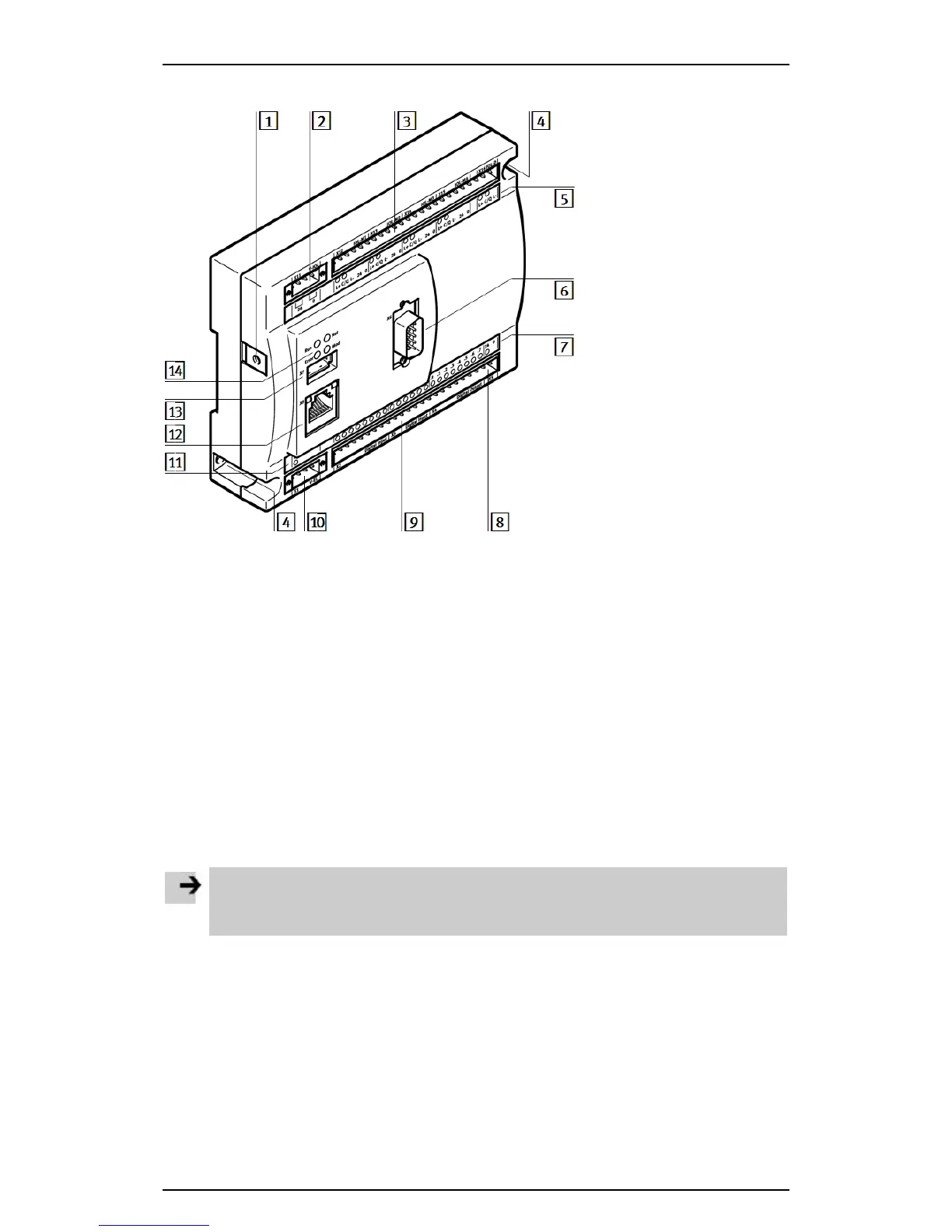
3.3 Connection and display components
1
Functional earth ’
8
I/O power supply
2
CECC-LK: Provides load voltage supply for IO-Link
CECC-S: Provides load voltage supply for IO-Link and power supply
for encoder
9
I/O interface
3
CECC-LK: IO-Link communication interface
CECC-S: ENC, RS232, RS422, RS485 and IO-Link communication
interfaces
aJ
Power supply to device
4
Mounting holes
aA
LED for power supply to
device
5
LEDs for communication interfaces
aB
Ethernet interface
6
CANopen interface
aC
USB interface
7
LEDs for I/O and
LED for power supply to I/O
aD
Status LEDs
Figure: Connection and display components
Note
Mixing up connections 2 and aJ can result in the destruction of the device.
• Make sure that the power supply to the device is only inserted at connection aJ.